Technical selection
Specifications and configuration
Reference — CGS series
| Parameter | Documented value / configuration |
|---|---|
| Engagement mechanism | Clamp-fastened push-to-lock couplingConditions: scope: supplier series structure; not an installed vibration certification |
| Listed temperature range | -55 to 120 degCConditions: scope: series summary; verify pressure and fluid for exact seal variant |
| Size specific recommended flow | CGS03 2.1; CGS05 5.88; CGS08 15; CGS10 23.55; CGS12 33.9; CGS15 53; CGS20 94.2 L/minConditions: scope: separate model rows, water 20 degC, plug-to-socket, 5 m/s velocity criterion; not one family rating |
| Documented ordering structure | Socket and plug codes, end connections and dimensions are tabulated separatelyConditions: scope: exact mating pair and end form to be specified; drawing governs |
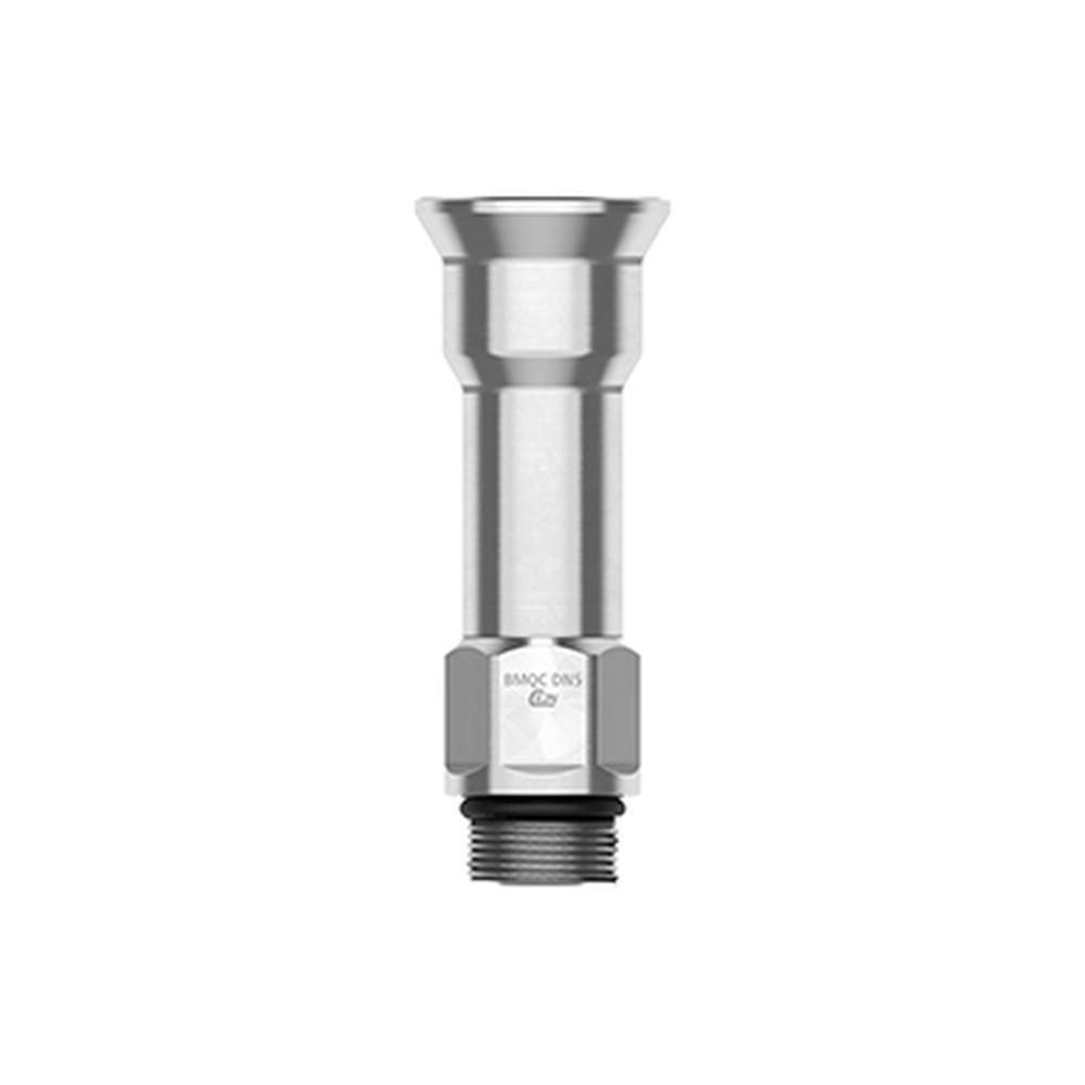
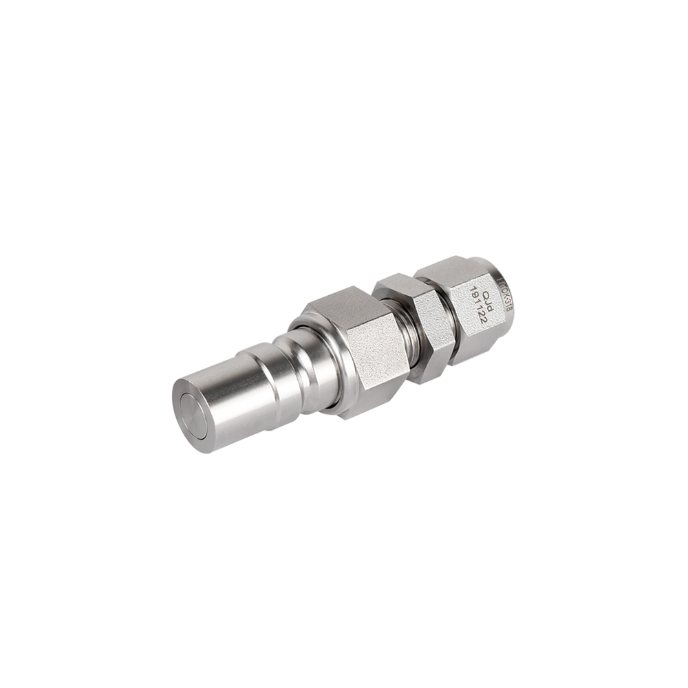
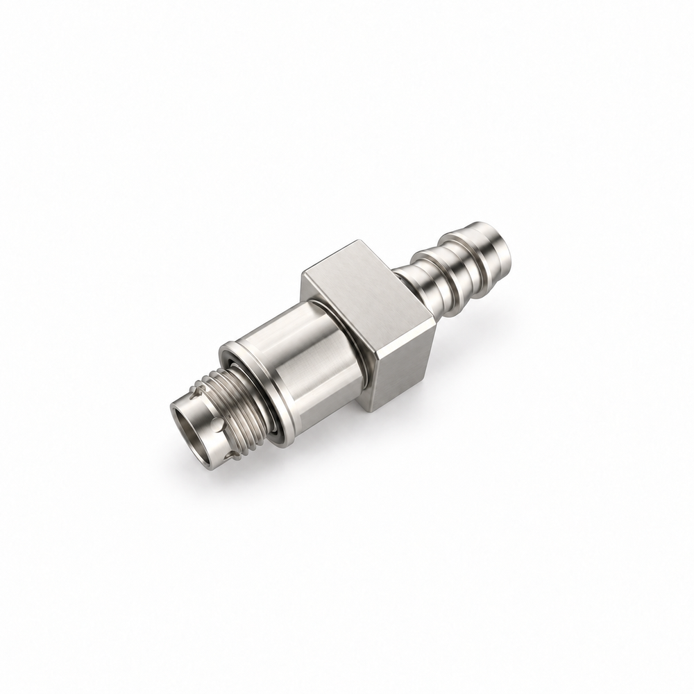
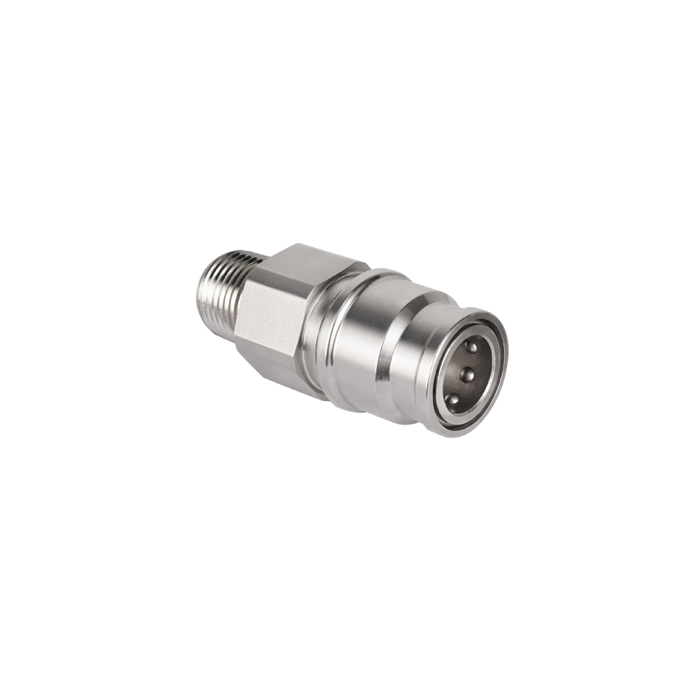
| Size specific socket plug end examples | The CGS03 socket table includes a stainless-code G1/8 male-thread example CGS03.1342-G18; the plug table separately lists 4 and 6 mm clamp-fastened hose-end examples, so the two ends must be ordered separatelyConditions: scope: Illustrative series options, not a pre-validated compatible pair or a port claim for the pictured example |
| Listed shell and seal options | CGS order-code tables separate aluminum-alloy and stainless-steel versions; series summary lists EPDM and FVMQ sealing-ring optionsConditions: scope: Selected material and seal follow exact order codes and require coolant review |
Manufacturer series reference. Confirm the exact order code, mating parts and stated conditions for the quoted configuration.
Overview
The CGS series uses a clamp-retained arrangement for a serviceable liquid connection where resistance to accidental release is an installation consideration. It remains a component pair, not a whole-rack retention system.
Construction and interfaces
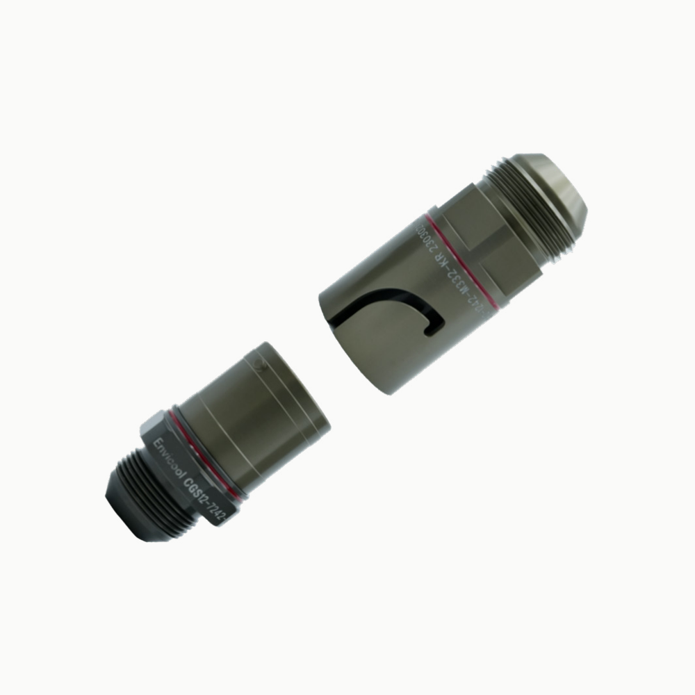
The source depicts separated halves and describes a compact push-to-lock construction with clamp fastening. Actual clamp hardware, end geometry, seal and body material require the chosen part-code drawings.
Selection
Compare the selected CGS size against its own recommended water-flow row and pressure-drop curve. The values in the official table are measured under specified direction, temperature and water conditions and are not a universal flow promise.
Configuration options
The catalogue lists distinct socket and plug codes, port connections and dimensions across CGS sizes. Define a matched combination, clamp assembly, service clearance and any inlet/return colour convention.
Application limits
A supplier description of anti-vibration purpose is not a certification for an installed loop. Its series temperature span does not settle pressure, seal compatibility or wetting-material limits for a selected configuration.