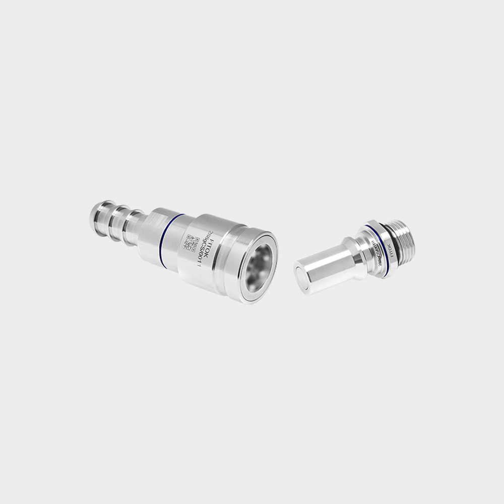
Universal Quick Disconnects (UQD)
Quick disconnect enquiries referencing a specified UQD interface and revision, with the mating configuration defined for review.
Explore rangeProduct family
Hand-mate and equipment-facing liquid couplings selected around interface, service, and fluid requirements.
Narrow your selection
Quick disconnect enquiries referencing a specified UQD interface and revision, with the mating configuration defined for review.
Explore rangeRack or equipment connections intended to mate through controlled alignment rather than direct hand access.
Explore rangeComponent selection
27 local draft records. Includes unfinished records and Family overviews. Draft · Noindex. Reference configurations are not approved stock. Image public-use review remains separate.
Show content-ready drafts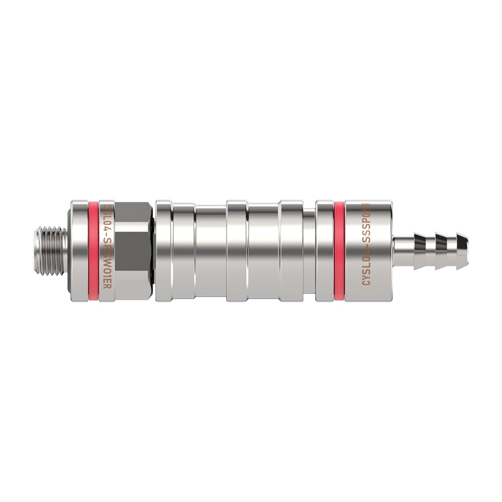
LCP-000009
A push-to-connect, ball-locking hand-mate coupling series illustrated by a CYSL04 reference, with documented body material and size range but unconfirmed seal and…
Component overview
A candidate family page for rack or equipment interfaces with controlled alignment.
LCP-000021
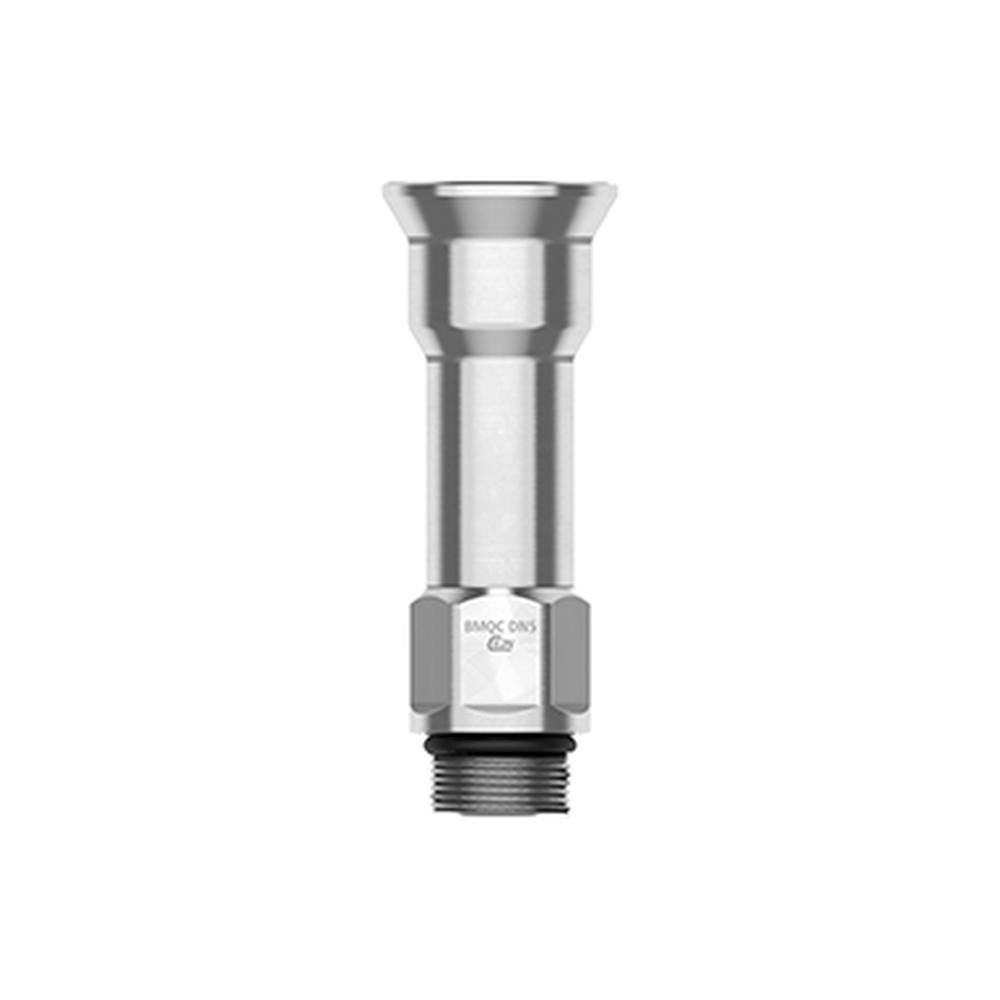
A CEJN BMQC blind-mate socket and plug with documented 5 mm nominal diameter, distinct ends and manufacturer alignment conditions that need rack-level…
LCP-000074
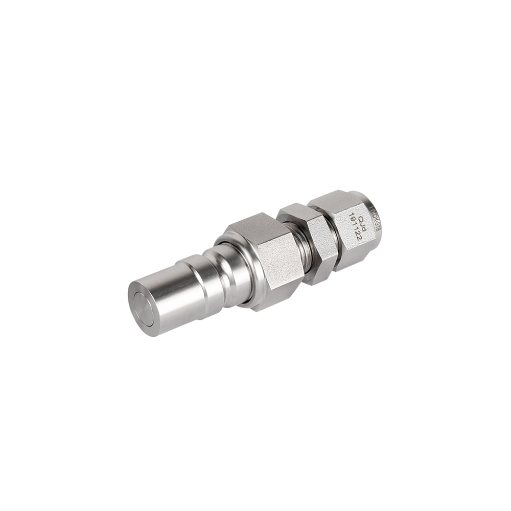
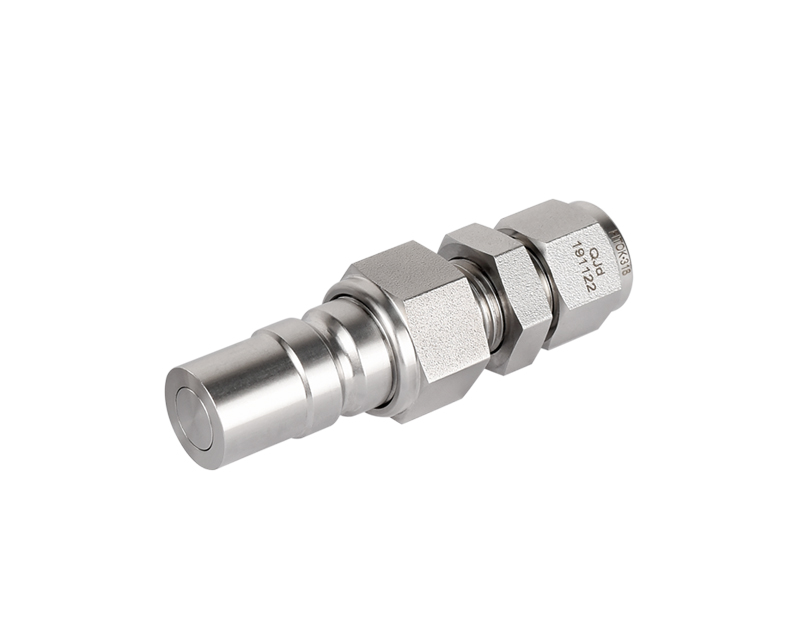
An exact QP8 stem/plug half with a 3/8 in bulkhead double-ferrule tube connection and EPDM seal. The official standalone image clearly shows…
LCP-000017
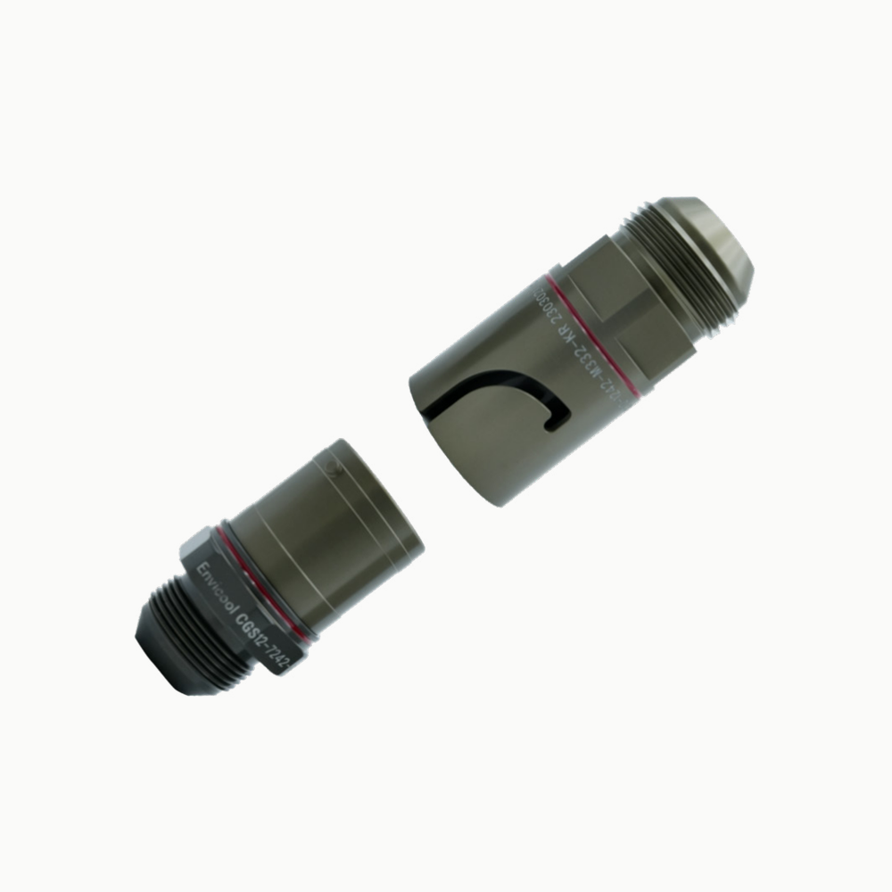
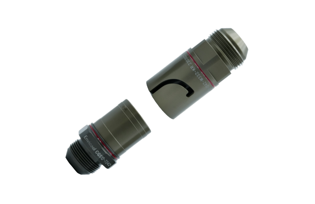
A CGS direct-insertion coupling pair with an additional clamp-retention concept and size-specific hydraulic catalogue rows, shown in an official series rendering.
Component overview
A candidate family page for requirements-led quick-disconnect configuration.
LCP-000014
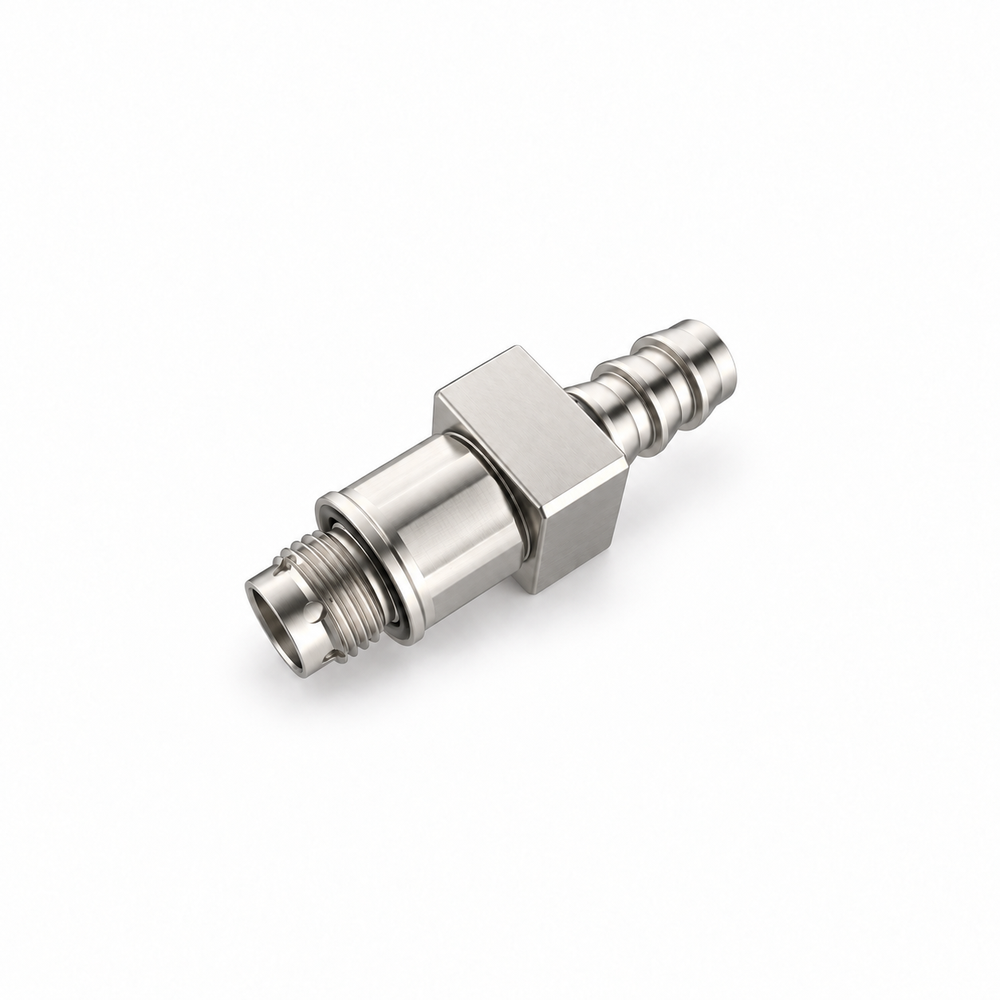
A separately pictured MQDB blind-mate construction with no integral lock, documented alignment guidance and model-specific flow and socket-end examples from an official…
LCP-000008
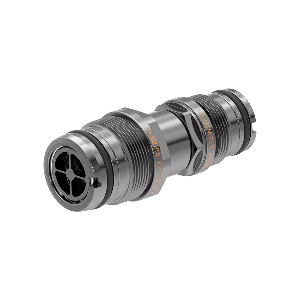
A fixed-style blind-mate coupler series illustrated by a CYSBI08 example, intended for guided equipment mating with external locking and explicit mounting-tolerance review.
LCP-000073
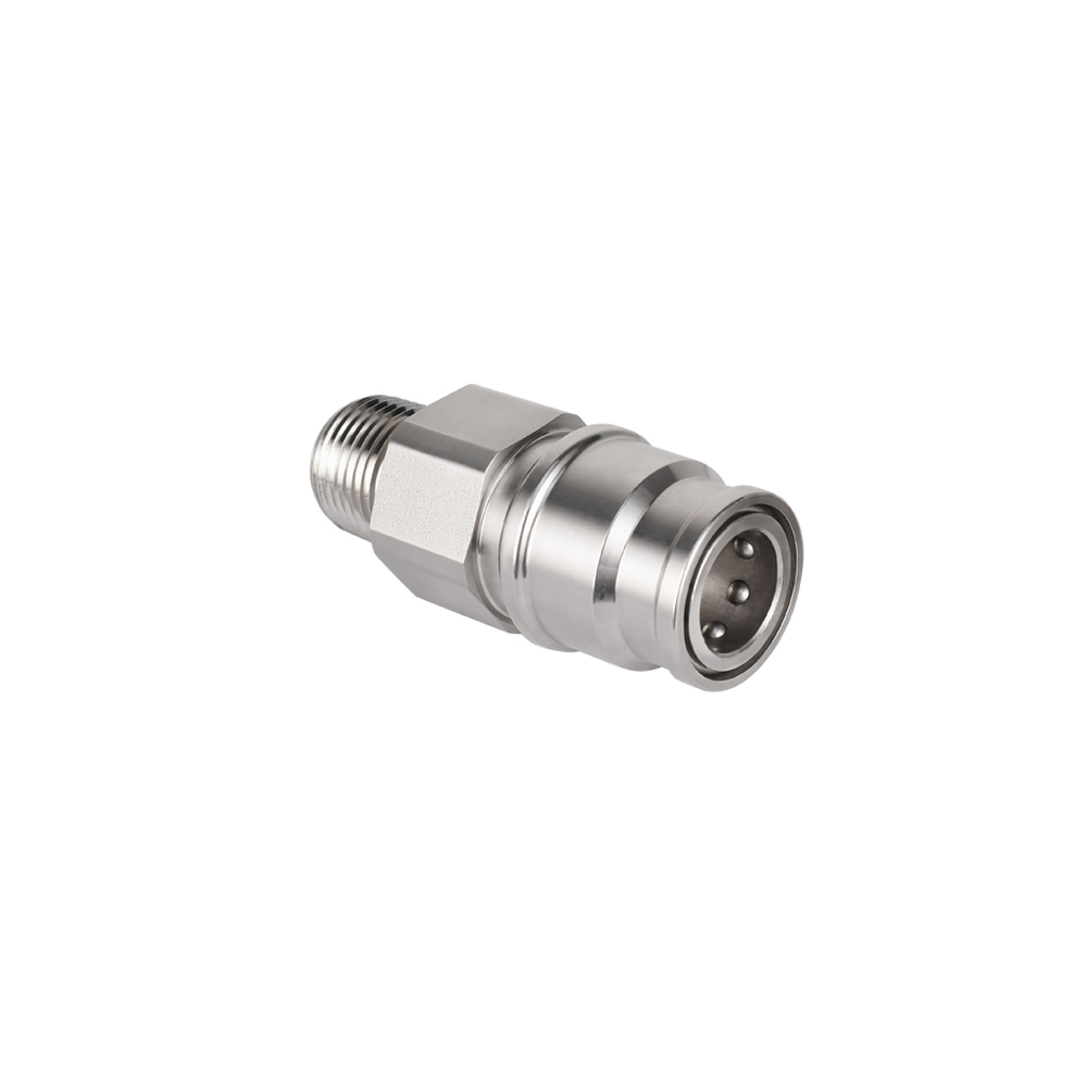
An exact QP8 socket/body half with a 1/2 in NPT male threaded tail, FKM seal and 316 stainless termination. Its official 800…
LCP-000016
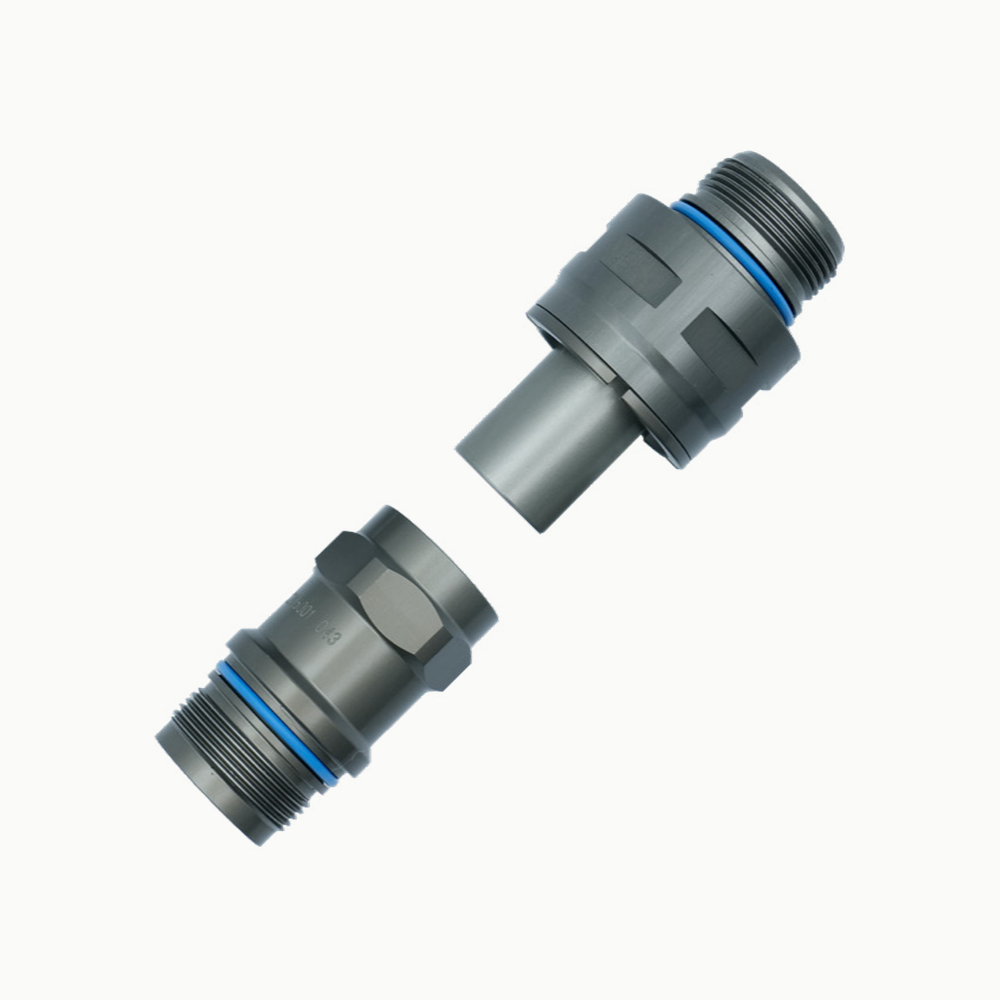
A distinct CGB floating blind-mate socket-and-plug reference with external fastening, documented alignment claim and model-separated water-flow rows; not interchangeable by name with…
LCP-000007
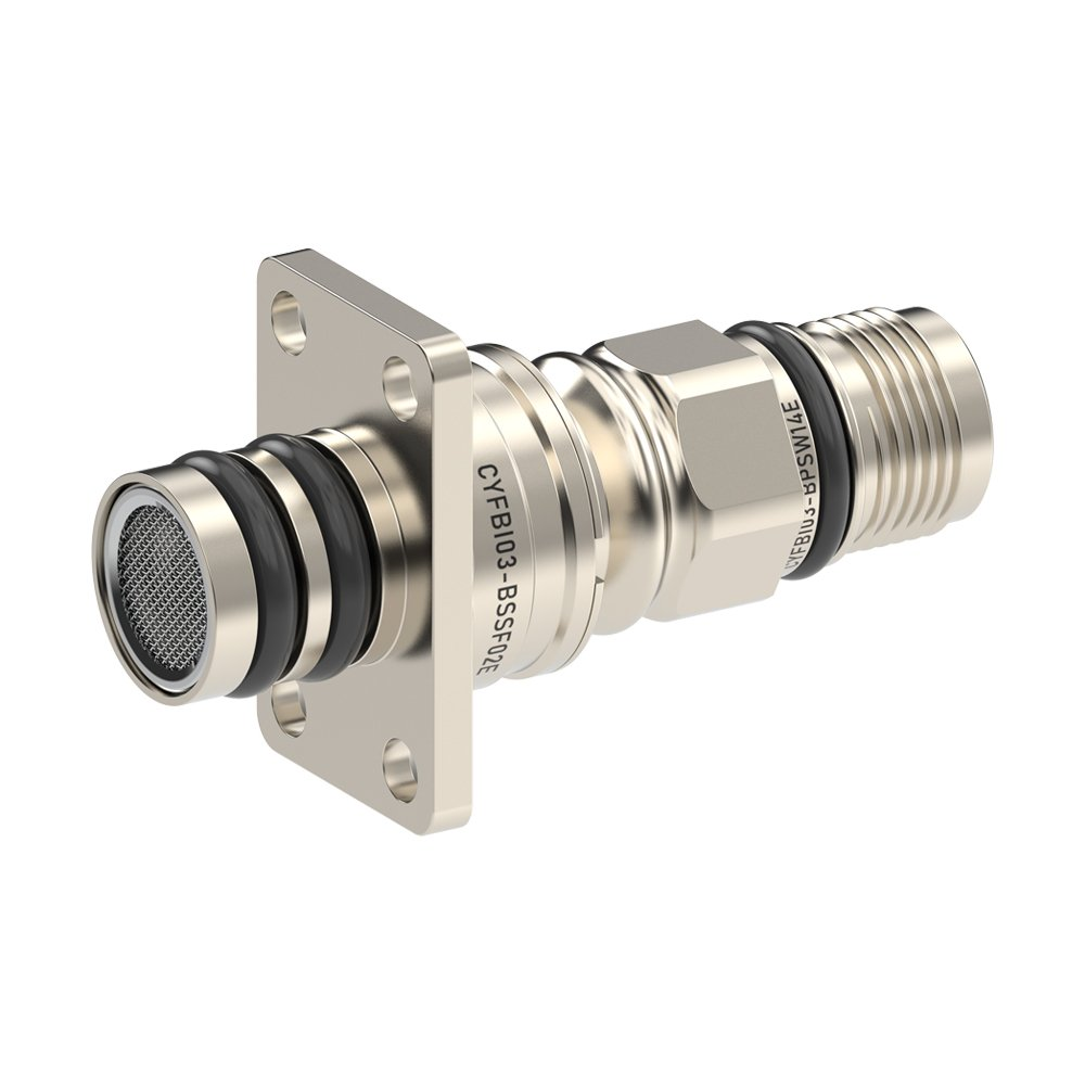
A floating blind-mate coupler series illustrated by a CYFBI03 example, with a documented external-retention requirement and manufacturer-stated misalignment accommodation that needs exact…
LCP-000120
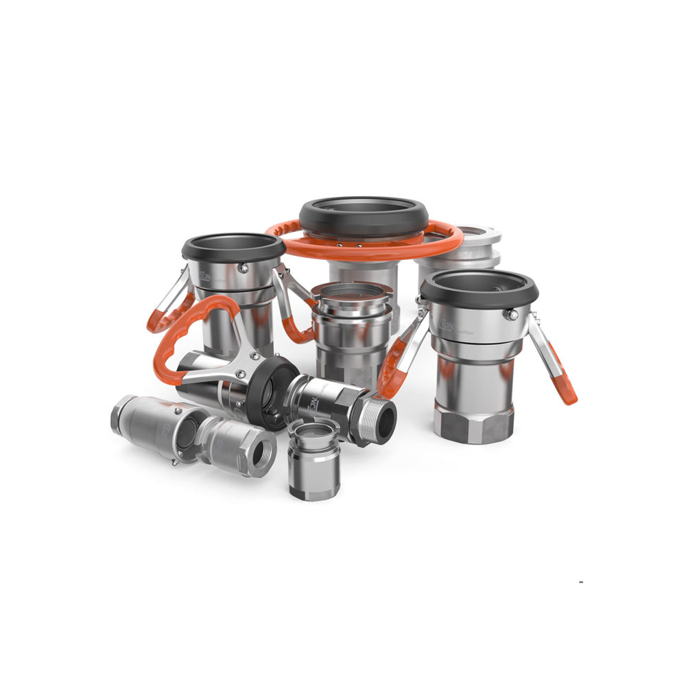
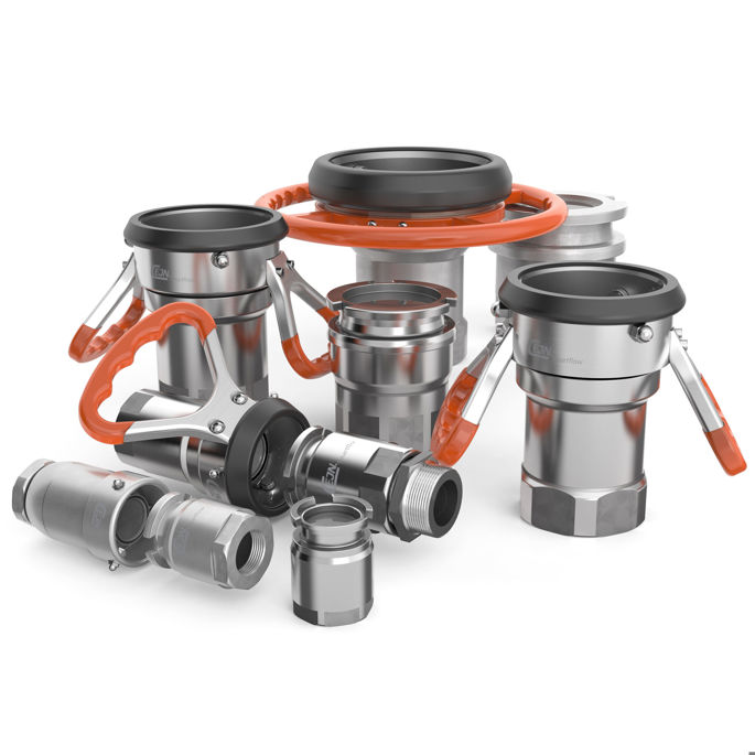
A large-bore dry-break fluid-transfer connector with handled hose unit and matching tank unit. The manufacturer range photo shows its turn-lock mechanism and…
LCP-000018
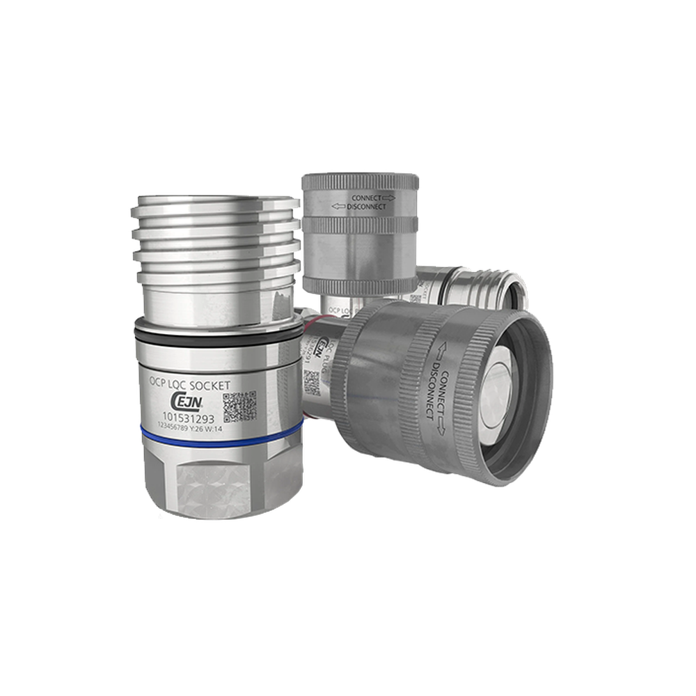
A documented G1 socket-and-plug LQC reference for CDU-side liquid lines, with separate CEJN part numbers and catalogue-scoped bore, seal and pressure data.
LCP-000118
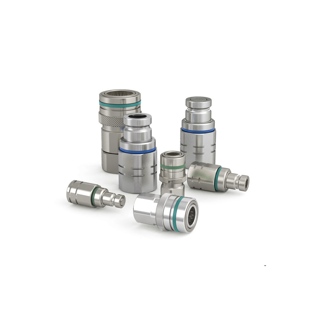
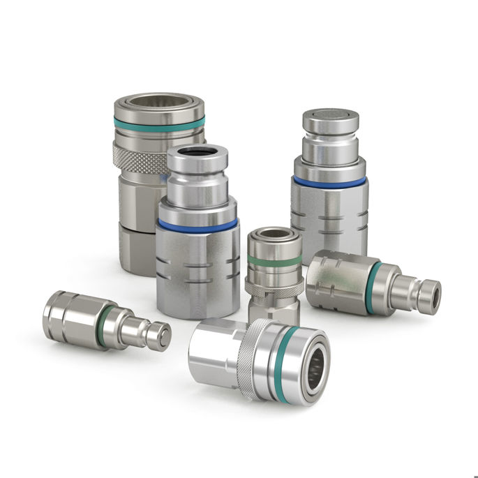
A manually operated non-drip quick-coupling family with matching socket and nipple forms. The original series photo shows several complete connection halves; select…
LCP-000022
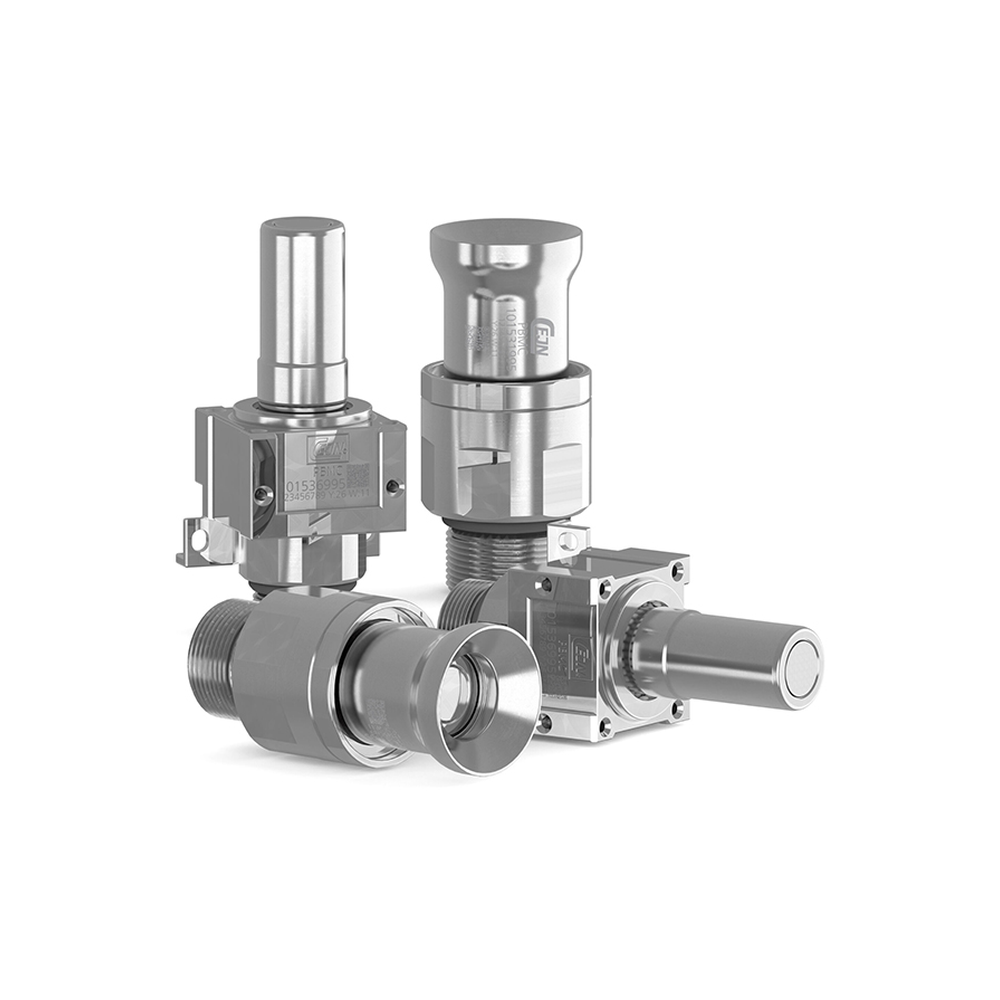
A distinct PBMC pivoting blind-mate coupling with fixed rear connections, self-centering engagement and manufacturer-scoped diameter, pressure and main-material data.
LCP-000015
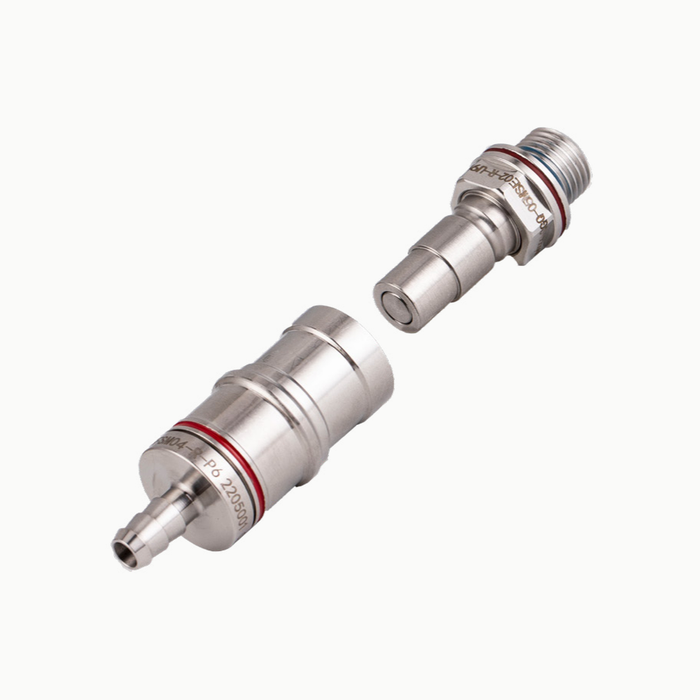
A two-part direct-insertion CGQ reference with a steel-ball locking mechanism and multiple documented model sizes, distinguished from steel-pin MQD and external-retention blind-mate…
LCP-000010
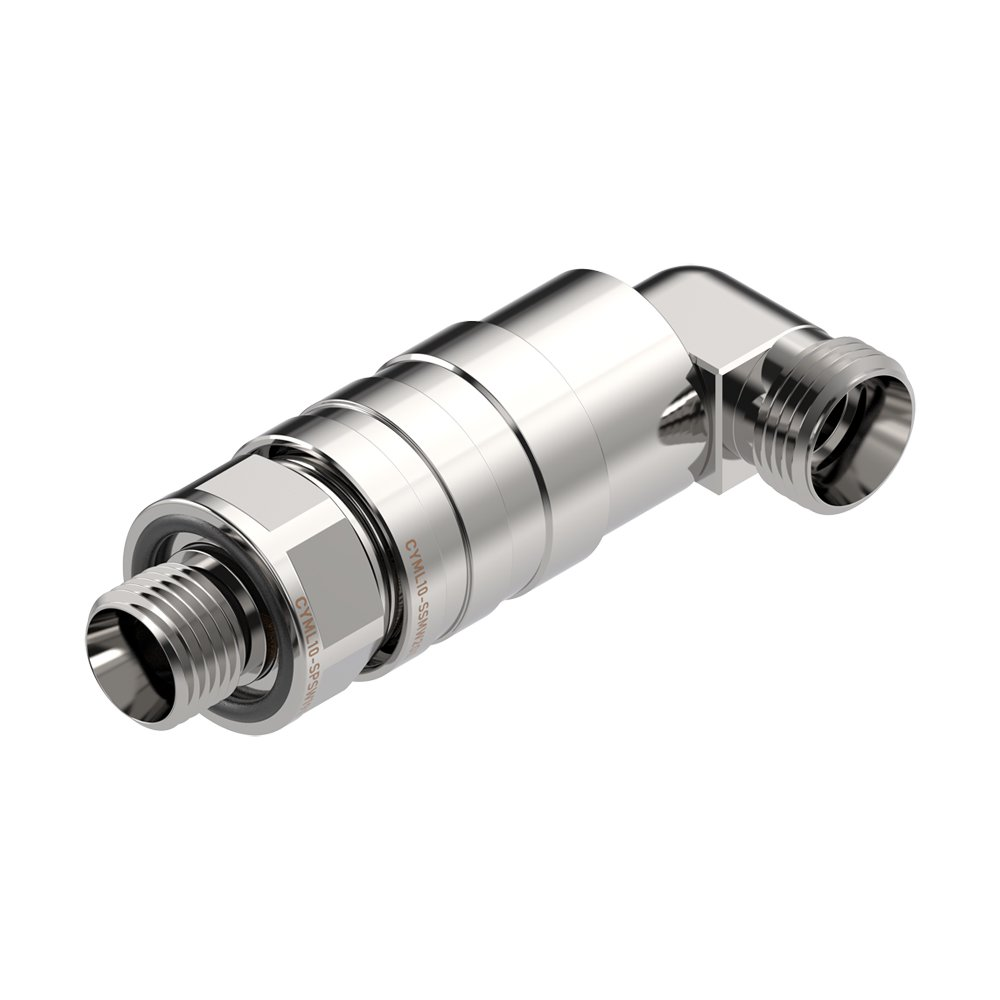
A semi-locking 316 stainless-steel coupling series illustrated by a CYML10 unit; the supplier describes external double O-rings, but seal material and coolant…
LCP-000011
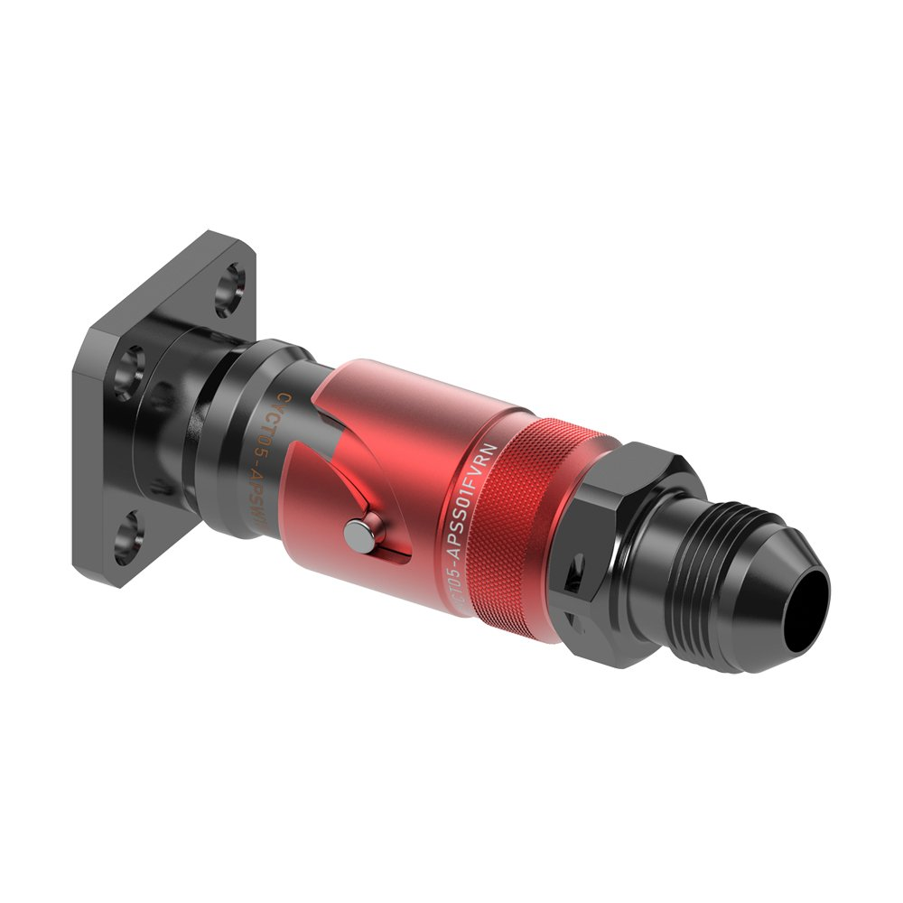
A latch-locking push-to-connect coupling series illustrated by a CYCT05 unit, with a visible retention mechanism and supplier-described aluminum body but no inferred…
LCP-000119
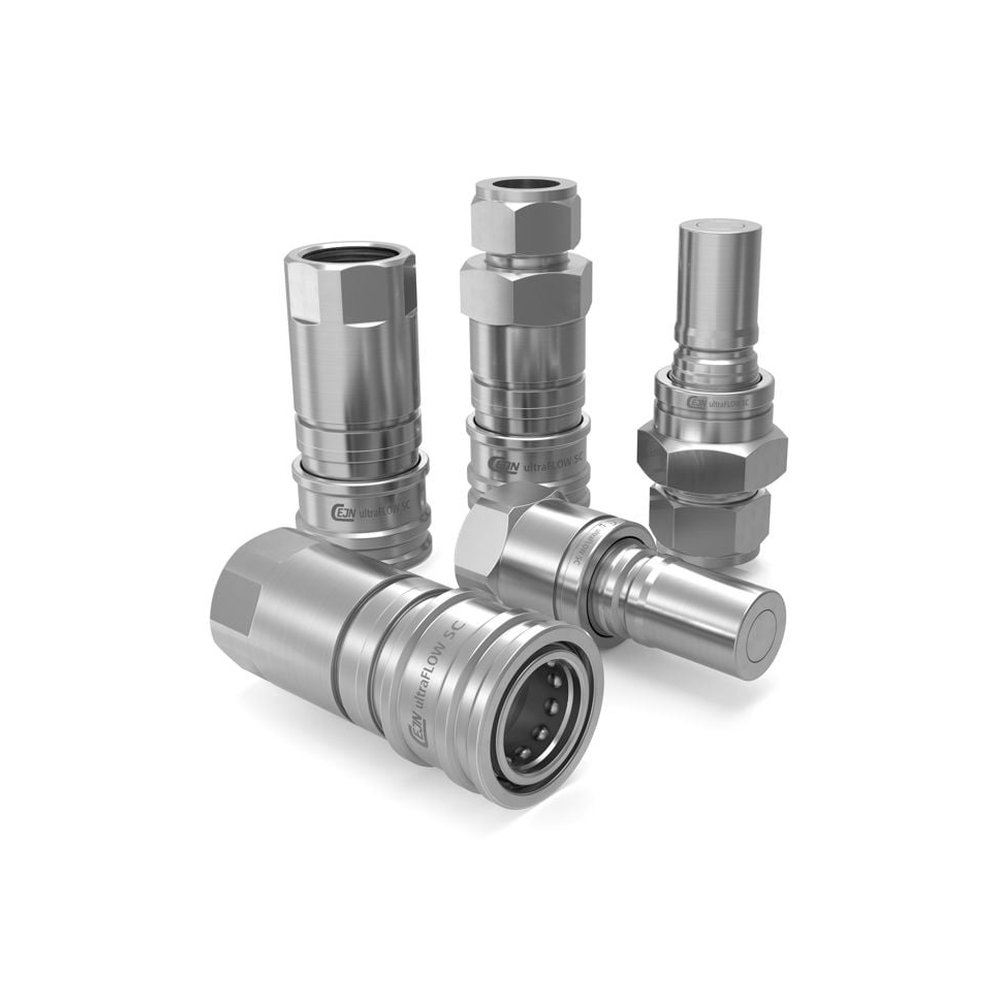
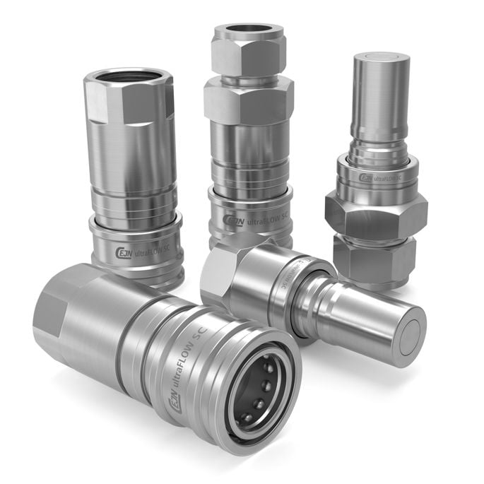
A stainless flat-face ultraFLOW SC connector family using threaded or double-ferrule tube ends. The distinct end-connection architecture supports liquid-loop assemblies where the…
LCP-000013
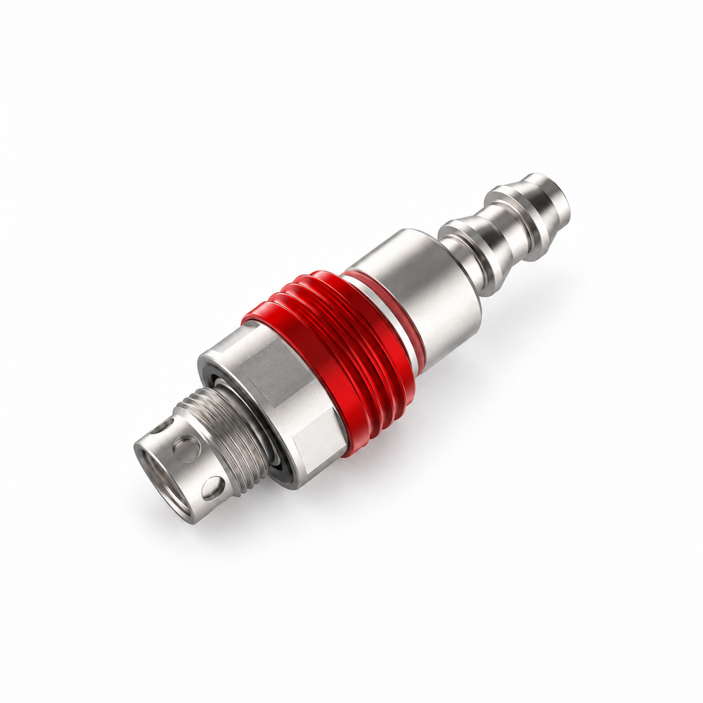
A compact direct-insertion liquid-cooling coupling with a distinct steel-pin lock, shown as an MQD manufacturer reference with separate size rows and end-connection…
Component overview
A candidate UQD-family page that requires an exact interface revision for every enquiry.
LCP-000001
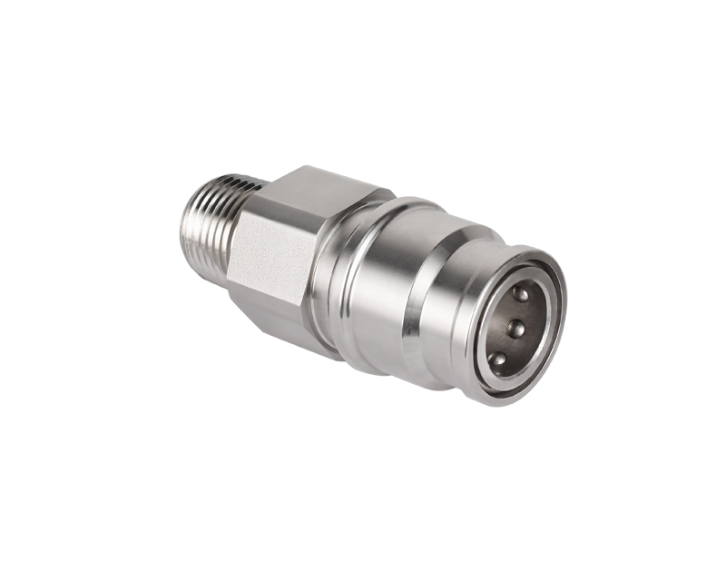
A small-format valved quick-disconnect arrangement for serviceable liquid-loop connections; the pictured series is a visual reference, while interface and flow values belong…
LCP-000019
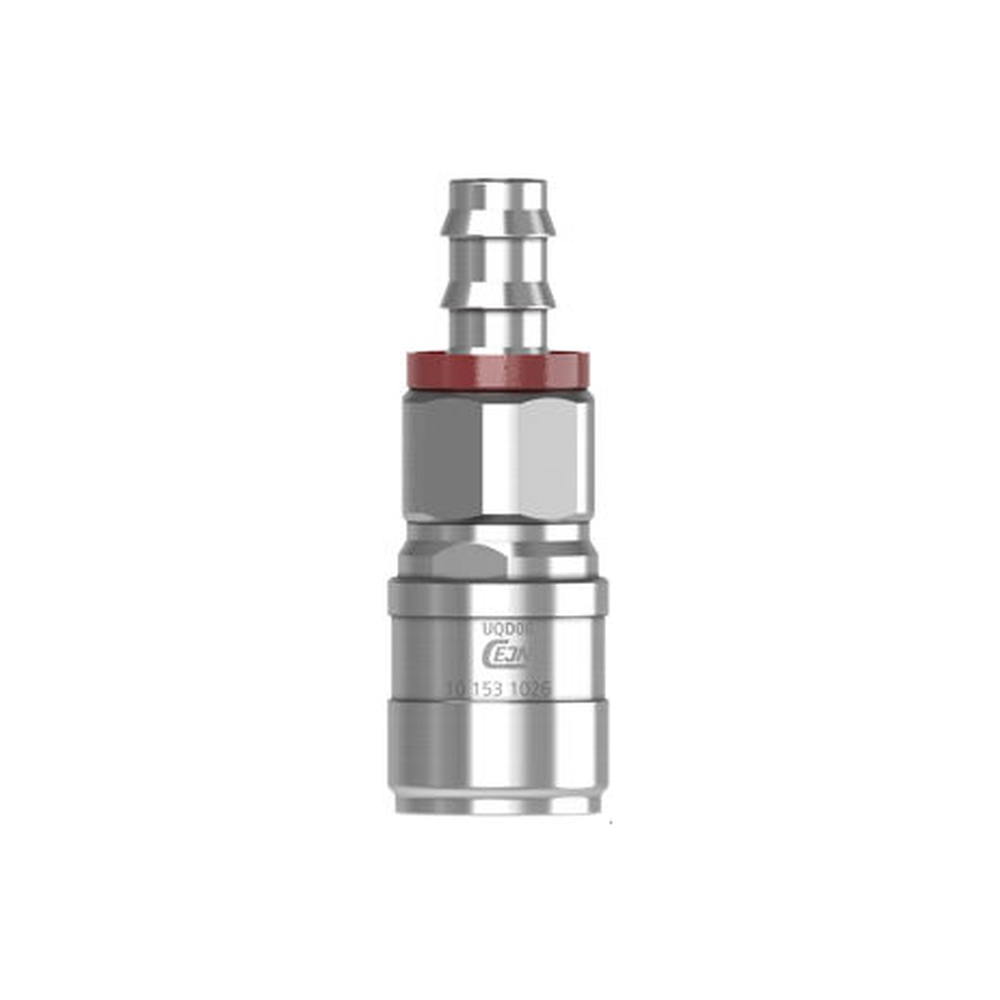
A size-specific UQD06 socket and plug example using two CEJN red-coded part numbers; their different hose and thread ends are kept explicit…
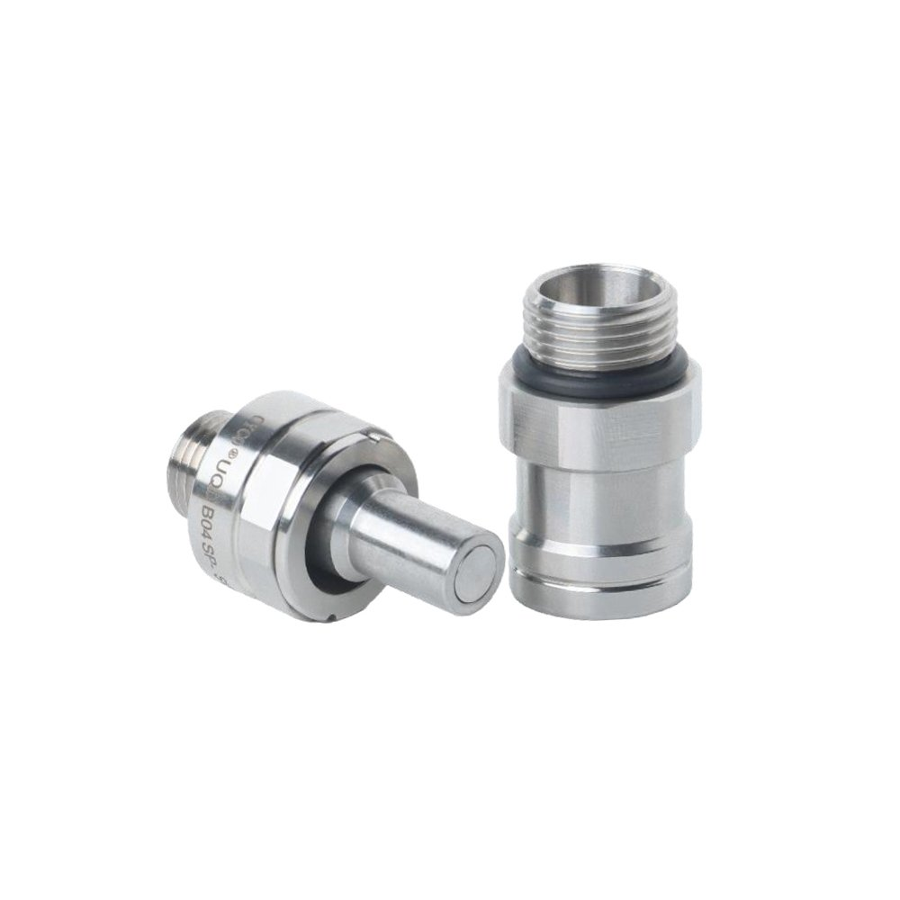
LCP-000006
A pictured UQDB04-size blind-mate socket and plug reference for serviceable liquid-cooling connections, with documented model-row interface and hydraulic coefficients rather than an…
Specify with confidence
Hand-mate or blind-mate installation and service sequence Plug/socket arrangement, port or thread, and hose/tube size Coolant and concentration, wetted materials and temperature Working pressure, flow and allowable pressure drop with stated conditions Disconnection leakage requirement, mounting envelope and quantity
Quick disconnect couplings provide a serviceable connection in a liquid loop. Selection starts with the mating pair, connection size and service sequence; fluid, pressure and leakage requirements then define the configuration to review.
Compare hand-mate and equipment-facing arrangements separately. Specify both halves, the port or hose termination, material and seal requirements, mounting space and expected disconnect condition.
Include the drawing or specification revision and identify any requirements that are still to be confirmed. Available configurations, testing and documentation are confirmed with quotation.
Local editorial preview
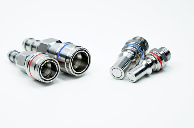
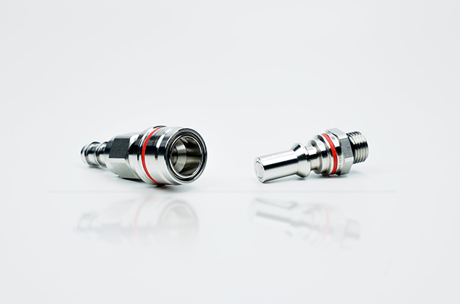
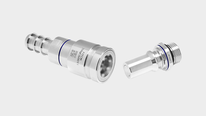
Manufacturer examples retain their model and conditions. These references describe source products, not approved stock or supply. Images are pending final selection and rights review.
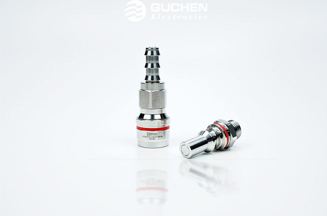
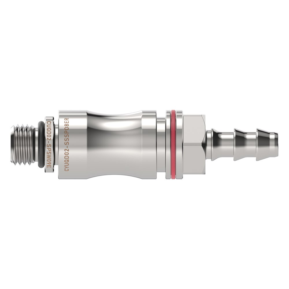
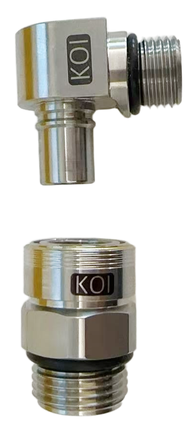
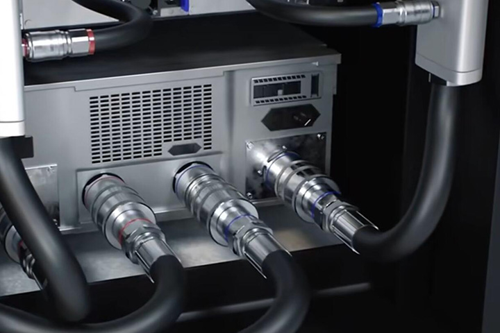
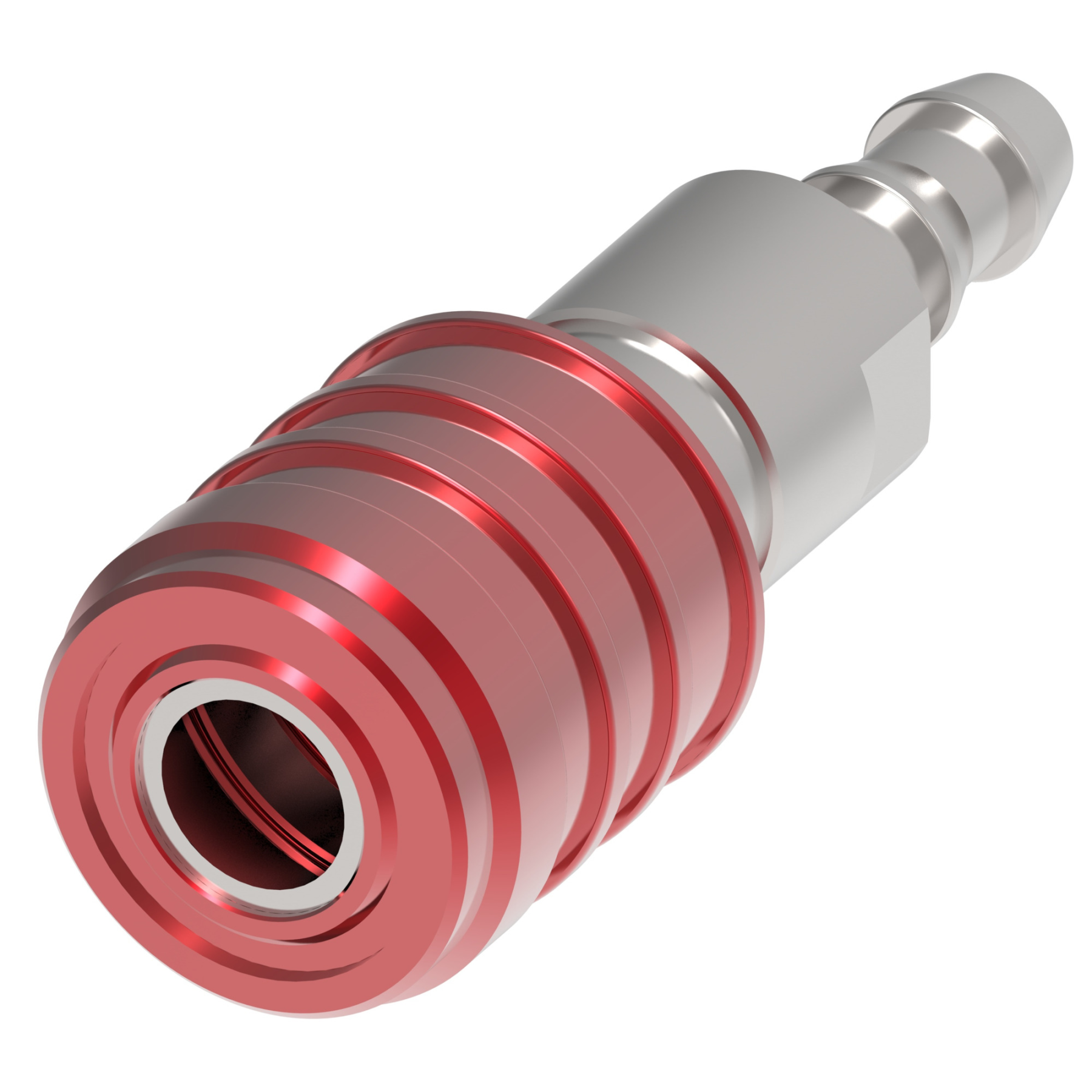
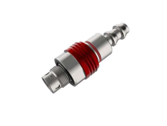
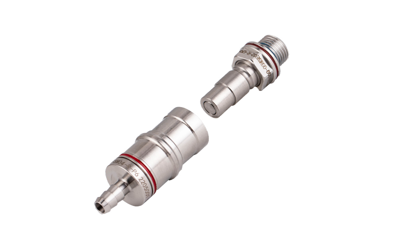
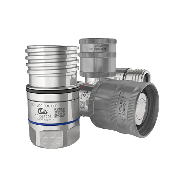
| Parameter | Documented value / configuration |
|---|---|
| Interface designation | UQD02 |
| Port connection | 1/4 in locking hose barb socket; SAE-4 threaded plug |
| Hose size | 1/4 in ID (6.4 mm ID) |
| Flow | Cv max: 0.37; Kv approx: 0.32; nominal flow path: 1/8 in |
| Working pressure | Vacuum to 120 psi (8.3 bar)Conditions: manufacturer warning: termination, fluid, temperature and environment affect performance |
| Temperature | 2 to 75 degrees C (36 to 167 degrees F) |
| Disconnect state | Valved dry-break connection; manufacturer describes disconnect under pressure with no spills. |
| Leakage behavior | Spillage less than 0.015 cc per disconnect at 0 psiConditions: pressure: 0 psi |
| Wetted material | 303 stainless steel housing; high-performance polymer valves; stainless steel wetted spring; EPDM seals |
| Mounting | Inline |
| Parameter | Documented value / configuration |
|---|---|
| Effective diameter options | DN3 to DN8Conditions: scope: series range; exact part needed |
| Body material | 316 stainless steelConditions: scope: body, not full wetted-material list |
| Locking mechanism | Ball-locking push-to-connect mechanismConditions: scope: manufacturer series description |
| Listed operating temperature | -40 to +125 degCConditions: scope: website series summary; seals, coolant and pressure-temperature pairing not provided |
| Parameter | Documented value / configuration |
|---|---|
| Effective diameter options | DN3 to DN10Conditions: scope: series range; exact part needed |
| Body material | 316 stainless steelConditions: scope: body, not full wetted-material list |
| Seal arrangement | External double O-rings described for shock absorption and cushioningConditions: scope: elastomer grade and fluid compatibility not stated |
| Locking mechanism | Semi-locking hand-mate mechanismConditions: scope: manufacturer series description |
| Listed working pressure | 0 to 20 barConditions: scope: Manufacturer series summary; verify selected halves, fluid and pressure-temperature pairing |
| Listed operating temperature | -40 to +125 degCConditions: scope: Manufacturer series summary; seal elastomer is not specified by this value |
| Parameter | Documented value / configuration |
|---|---|
| Effective diameter options | DN3 to DN12Conditions: scope: series range; exact part needed |
| Body material | Aluminum alloyConditions: scope: body, not full wetted-material list |
| Locking mechanism | Latch-locking, push-to-lock engagementConditions: scope: manufacturer series description |
| Listed operating temperature | -40 to +125 degCConditions: scope: website series summary; seals, coolant and pressure-temperature pairing not provided |
| Parameter | Documented value / configuration |
|---|---|
| Engagement mechanism | Steel-pin locking with direct insertionConditions: scope: manufacturer series description, not a cross-brand mating standard |
| Listed working pressure | 0 to 100 psiConditions: scope: series statement; exact order code, fluid and temperature must be verified |
| Listed temperature range | -40 to 110 degCConditions: scope: not a combined pressure-temperature-coolant operating envelope |
| Size specific recommended flow | MQD02 2.1; MQD03 4.6; MQD04 8.5; MQD04 MINI 8.5 L/minConditions: scope: separate model rows, water at 20 degC, plug-to-socket direction, manufacturer 5 m/s velocity criterion; not one family flow range |
| Size specific socket plug end examples | For MQD02, the catalog lists socket MQD02-1432-U716 with UNF 7/16-20 and plug MQD02-7434-P7 with a 7 mm end; these are separate matching-half examples, not a universal MQD portConditions: scope: Order specific; confirm half pairing, mating drawing and tube/hose connection |
| Listed shell and seal options | MQD technical summary lists SUS316L shell and EPDM or FVMQ sealing-ring optionsConditions: scope: Series-listed options; verify actual wetted set and coolant compatibility by order code |
| Parameter | Documented value / configuration |
|---|---|
| Engagement mechanism | Steel-ball locking with direct insertionConditions: scope: semi-automatic manufacturer series description |
| Listed temperature range | -55 to 120 degCConditions: scope: series summary; pressure, coolant and seal pairing require exact variant review |
| Size specific recommended flow | CGQ03 2.1; CGQ04 3.8; CGQ05 5.9; CGQ06 8.5; CGQ08 15.1; CGQ10 23.5; CGQ12 33.9; CGQ15 53; CGQ20 94.2; CGQ25 135 L/minConditions: scope: separate model rows, water 20 degC, plug-to-socket, 5 m/s velocity criterion; not one rating |
| Documented connection variants | Threaded socket and plug options are shown separately by CGQ size and part codeConditions: scope: mating half and end geometry must match one controlled order code |
| Size specific socket plug end examples | CGQ03 stainless-code socket CGQ03.1342-G18 and plug CGQ03.7342-G18 are separately tabulated with G1/8 male-thread ends; other size, material and hose-end codes differConditions: scope: Example pair rows only, not proof every CGQ half or depicted image uses G1/8 |
| Listed shell and seal options | CGQ order-code tables separate aluminum-alloy and stainless-steel columns; series summary lists EPDM and FVMQ sealing-ring optionsConditions: scope: Material and seal depend on selected half codes; wetted compatibility not universal |
| Parameter | Documented value / configuration |
|---|---|
| Engagement mechanism | Clamp-fastened push-to-lock couplingConditions: scope: supplier series structure; not an installed vibration certification |
| Listed temperature range | -55 to 120 degCConditions: scope: series summary; verify pressure and fluid for exact seal variant |
| Size specific recommended flow | CGS03 2.1; CGS05 5.88; CGS08 15; CGS10 23.55; CGS12 33.9; CGS15 53; CGS20 94.2 L/minConditions: scope: separate model rows, water 20 degC, plug-to-socket, 5 m/s velocity criterion; not one family rating |
| Documented ordering structure | Socket and plug codes, end connections and dimensions are tabulated separatelyConditions: scope: exact mating pair and end form to be specified; drawing governs |
| Size specific socket plug end examples | The CGS03 socket table includes a stainless-code G1/8 male-thread example CGS03.1342-G18; the plug table separately lists 4 and 6 mm clamp-fastened hose-end examples, so the two ends must be ordered separatelyConditions: scope: Illustrative series options, not a pre-validated compatible pair or a port claim for the pictured example |
| Listed shell and seal options | CGS order-code tables separate aluminum-alloy and stainless-steel versions; series summary lists EPDM and FVMQ sealing-ring optionsConditions: scope: Selected material and seal follow exact order codes and require coolant review |
| Parameter | Documented value / configuration |
|---|---|
| Documented mating part numbers | Socket 10 153 1290; plug 10 153 6290Conditions: scope: manufacturer order-code examples; both halves require confirmation |
| End connections | G 1 inch socket; G 1 inch plugConditions: scope: these two listed part numbers only |
| Nominal flow diameter | 19 mmConditions: scope: each listed half, not a measured flow rate |
| Manufacturer max working pressure | 12 barConditions: scope: manufacturer catalogue rating for both listed parts; validate selected coolant, temperature and installed assembly |
| Listed seal material | EPDMConditions: scope: these two listed part numbers only; coolant compatibility not inferred |
| Coupling mechanism | Screw-to-connect locking mechanismConditions: scope: manufacturer series construction; not interchangeability proof for a mixed-brand pair |
| Parameter | Documented value / configuration |
|---|---|
| Connection role | QP8 flat-face quick-connect body/socket halfConditions: scope: Exact manufacturer product page and photographed half; mating stem is a separate item |
| Port connection | 1/2 in NPT male threadConditions: scope: Exact listed end connection |
| Termination material and seal | 316 stainless steel end material; FKM O-ringConditions: scope: Manufacturer page listing; verify the complete wetted set and coolant for the selected pair |
| Published operating reference | 20 bar (290 psig) and -20 to 200 °C listed on the product pageConditions: scope: Maker-listed half/series reference; actual mating pair, seal and coolant may impose lower limits |
| Published pair cv | Cv 0.9 listed for QP8 seriesConditions: scope: Published QP8 stem-to-body test direction; end fitting can reduce Cv and isolated half is not independently rated |
| Parameter | Documented value / configuration |
|---|---|
| Connection role | QP8 flat-face quick-connect stem/plug half with bulkhead mountingConditions: scope: Exact manufacturer product page and photographed half; mating body is a separate item |
| Port connection | 3/8 in bulkhead double-ferrule tube fittingConditions: scope: Exact listed end connection |
| Termination material and seal | 316 stainless steel end material; EPDM O-ringConditions: scope: Manufacturer page listing; confirm compatible mating body and actual coolant |
| Published operating reference | 20 bar (290 psig) and -40 to 148 °C listed on the product pageConditions: scope: Maker-listed reference; mated pair and installed tube can have lower limits |
| Published pair cv | Cv 0.9 listed for QP8 seriesConditions: scope: Published QP8 stem-to-body test direction; port geometry may reduce Cv |
| Parameter | Documented value / configuration |
|---|---|
| Nominal flow diameter options | Nominal flow-diameter options 4, 6, 9, 14 and 19 mm across the series |
| Series max working pressure | 20 bar maximum working pressure stated for the series; confirm selected material, size, seal and temperature |
| Main material options | Nickel-plated brass and AISI 316 stainless-steel versions are described as separate material choices |
| Mating pair and valve configurations | Matching coupling and nipple halves are offered in double shut-off, single shut-off or straight-through configurations; optional color and key coding distinguish mating linesConditions: scope: Manufacturer series choices; a selected coupling and nipple must use matching codes and confirmed end connections |
| Catalogued socket plug end and seal example | Series 267 order example: coupling 10 267 1220 and nipple 10 267 6220 each list G 1/4 in (BSP) connection and EPDM seal. This example does not identify the photographed pair or cover other Non-Drip sizes.Conditions: Series 267 ordering example; scope: CEJN Series 267 order table example only |
| Parameter | Documented value / configuration |
|---|---|
| End connection options | Stainless ultraFLOW SC is described with threaded connection or double-ferrule tube fitting ends |
| Nominal flow diameter options | Nominal flow-diameter options 5, 10 and 12 mm across the series |
| Series max working pressure range | 10 to 20 bar maximum working pressure range across configurations, not one rating for every code |
| Mating pair role | Quick-connect coupling and matching nipple form a separable liquid-cooling line connection; the SC variant includes double-ferrule tube-fitting ends in the manufacturer's described configurationConditions: scope: Series description, not interchangeability with standard ultraFLOW or proof that every order code has ferrule ends |
| Main material options | Current CEJN ultraFLOW SC product page lists stainless steel and AISI 316 stainless steel as main material choices; an exact order code is needed to fix the wetted material grade.Conditions: scope: Current product-page series summary, not an individual photographed part |
| Documented seal and temperature reference | CEJN's 2023 ultraFLOW SC presentation specifies EPDM sealing and -30 to +150 °C for the presented series configuration; verify the selected current order code and coolant before using this range.Conditions: 2023 technical presentation; scope: Dated technical presentation; not a current catalogue guarantee for every SC code |
| Parameter | Documented value / configuration |
|---|---|
| Nominal flow diameter options | Nominal flow-diameter options 25, 50, 65, 80 and 100 mm across the series |
| Series max working pressure | 25 bar maximum working pressure stated for the series; actual complete duty must be checked for selected size/material/fluid |
| Main material options | Aluminum and stainless-steel constructions identified as series material options |
| Connection mechanism | Female hose unit twists approximately one-third turn onto male tank unit; integrated poppets open on engagement and close on release |
| Catalogued hose tank end options | The ordering table separates hose and tank units; for the 4 in stainless examples, hose unit 10 640 0003 and tank unit 10 640 5005 list G 4 in female ends, while 10 640 0004 and 10 640 5006 list 4 in NPT female ends. Select the two mating units by exact order code; the range photograph does not identify one of these codes.Conditions: Published ordering examples, not pictured order code; scope: CEJN Smartflow 4 in ordering examples; other sizes and materials have separate codes |
Selection resources

Selection guide
Define interface, service method, fluid conditions, materials, validation, and quantity before comparing coupling options.
Read guideSelection guide
Separate the service architecture from the exact connector interface before preparing an RFQ.
Read guide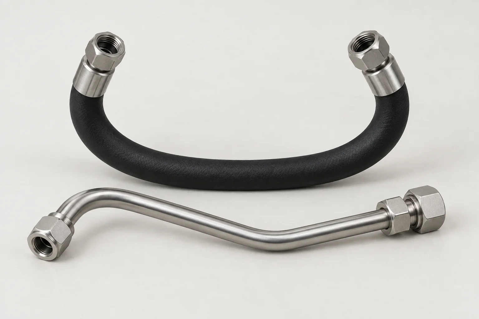
Selection guide
A practical checklist for routed liquid-cooling assemblies.
Read guide