Technical selection
Specifications and configuration
Reference — SMC KQG2H06-08
| Parameter | Documented value / configuration |
|---|---|
| Ordering code | KQG2H06-08; reducing straight tube unionConditions: scope: Exact catalogue row; image is series shape |
| Connection | 6 mm × 8 mm nominal tube outside diametersConditions: scope: Nominal tube ODs; confirm orientation and matching tubing |
| Effective area | 13.1 mm² effective sectional area with FEP tubeConditions: scope: Catalogue value stated for FEP tube; not flow rate |
| Series operating envelope | KQG2 series: water listed; −100 kPa to 1 MPa operating range; −5 to 150 °C without freezing; SUS316 metal partsConditions: scope: Series-level envelope; tube and seal choice may limit assembly |
Manufacturer series reference. Confirm the exact order code, mating parts and stated conditions for the quoted configuration.
Overview
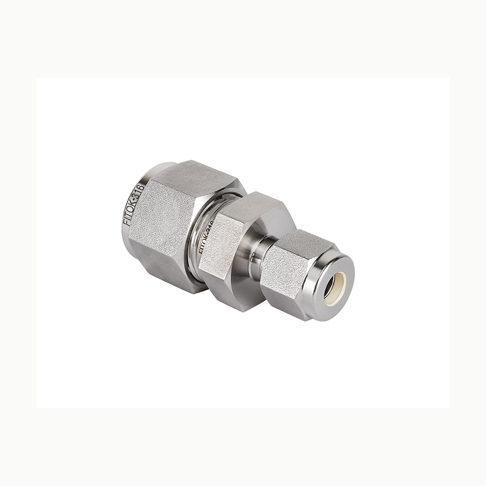
The reducing body joins two different tube outside diameters in a straight path. It is relevant when a rack branch steps between defined tube sizes rather than to compensate for an unspecified fitting mismatch.
Construction and interfaces
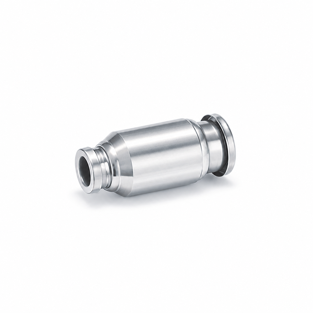
The manufacturer's table lists 6 mm and 8 mm nominal tube connections. Its low-resolution catalogue image shows a visible stepped straight body; KQG2 metal parts are listed as SUS316.
Selection
Confirm which end meets each tube on the circuit drawing. Check both tube materials and walls, insertion lengths, available release space and any allowable restriction at the size transition.
Configuration options
Other reduction pairs are separate KQG2H rows. Do not treat the 6-to-8 mm example as proof of every possible size or any site's available stock configuration.
Application limits
The effective sectional area is stated for the maker's FEP tube condition, not a complete hydraulic rating. Pressure and temperature at the assembled joint depend on tubing and fluid selection.