Technical selection
Specifications and configuration
Reference — FG-SYS
| Parameter | Documented value / configuration |
|---|---|
| Coverage | location accuracy m: 1; maximum per circuit m: 600; maximum total m: 1800 |
| Output | eight programmable alarm relays; power-fail relay; Modbus over RS232/RS422/RS485 |
| Alarm boundary | Panel reports leak or cable-break state; site shutdown/interlock logic remains a separate system design decision. |
| Test method | Built-in test function scans the system and connected cable lengths; commissioning acceptance needs a documented procedure. |
Manufacturer reference configuration. Values and conditions apply to the named reference; the supplied configuration requires separate confirmation.
Overview
This controller supervises connected leak-sensing cable circuits and reports leakage or cable-fault conditions to an external control system. It is a monitoring component, not proof of end-to-end leak prevention.
Construction and interfaces
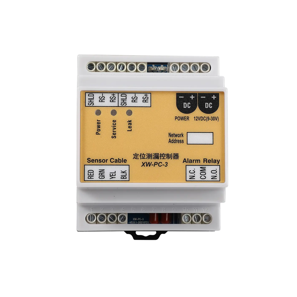
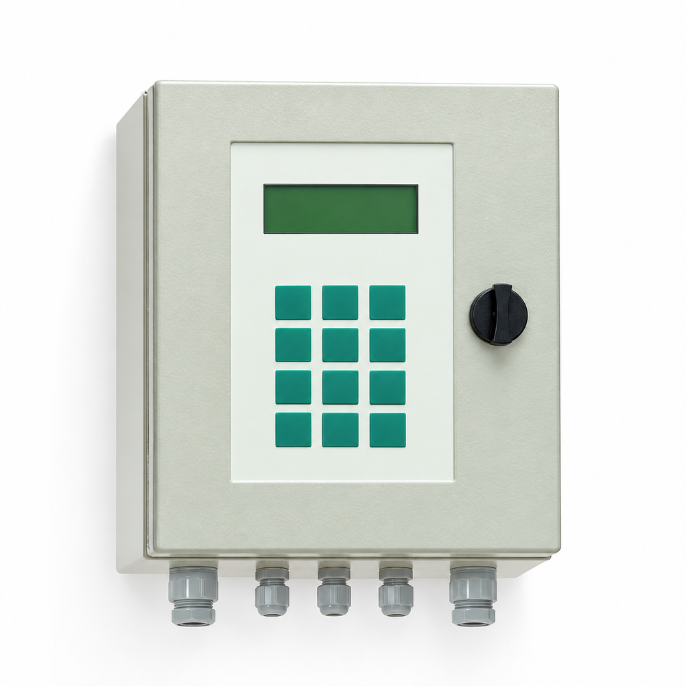
The pictured exact reference is a wall-mounted control enclosure with a local display and connection points for sensing and output wiring. Cable type, circuit layout and electrical supply must match the controlled installation documents.
Selection
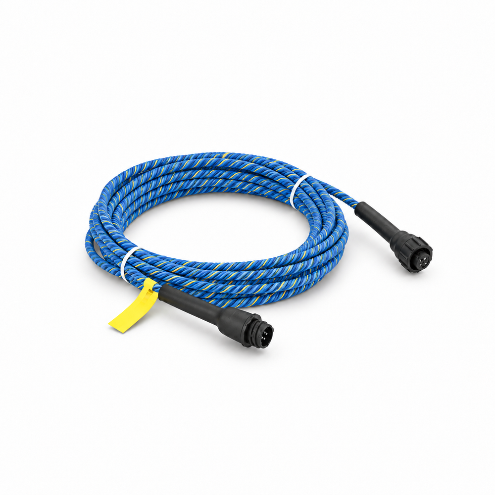
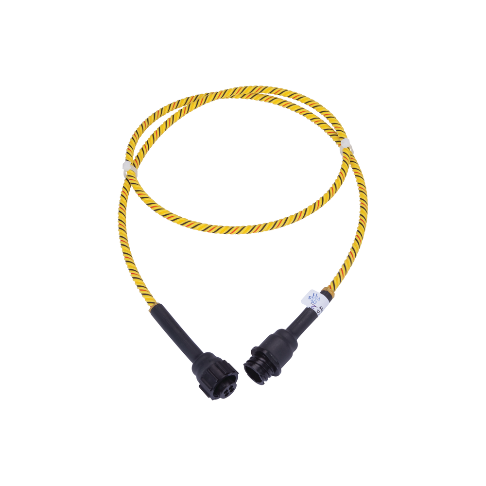
Design the cable coverage and circuit lengths around the actual equipment area, including service and maintenance access. Alarm relays and serial interfaces must be matched to the buyer's building or rack control architecture.
Configuration options
The documented controller supports multiple alarm outputs and serial communication paths. This does not mean every sensing cable, wiring topology or site interlock is included in the controller order.
Application limits
The controller reports an alarm state; shutdown logic, alarm routing, commissioning tests and response ownership are separate system decisions. Electrical power details require rechecking because the stored source text contains an encoding defect.