Technical selection
Specifications and configuration
Reference — XW-PC-3
| Parameter | Documented value / configuration |
|---|---|
| Model identity | XW-PC-3 locating leak detection controller |
| Monitored cable length | Up to 150 m with matching locating sensing cable |
| Supply voltage | DC 9–30 V; 12 V recommended |
| Signal interface | RS485 plus one dry-contact relay (NO/NC) |
| Response time | ≤8 s under maker's stated test context |
| Operating temperature | -40 to 70 °C |
Manufacturer reference configuration. Values and conditions apply to the named reference; the supplied configuration requires separate confirmation.
Overview
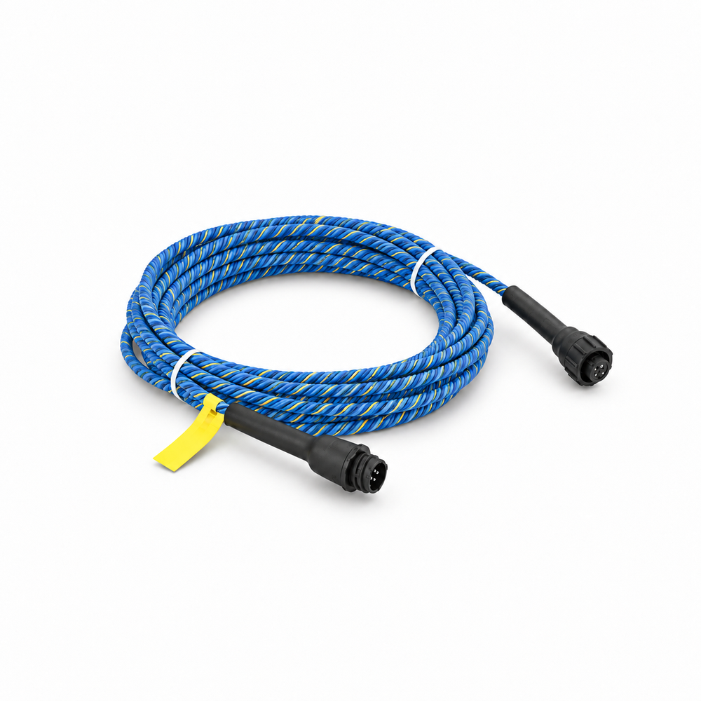
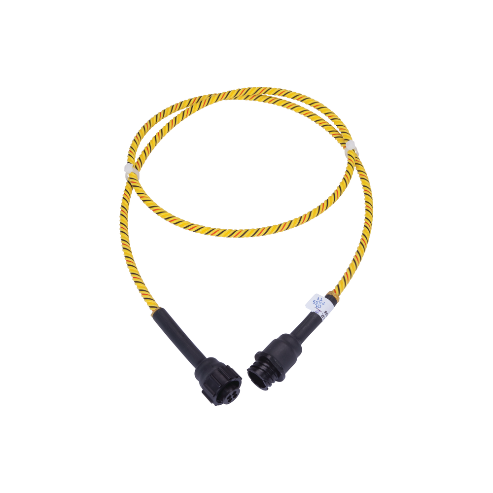
This controller supervises a compatible cable zone and reports a leak position, rather than directly sensing a spot on its own. It pairs naturally with a locating leak cable such as the documented XW-ES2 type after interface confirmation.
Construction and interfaces
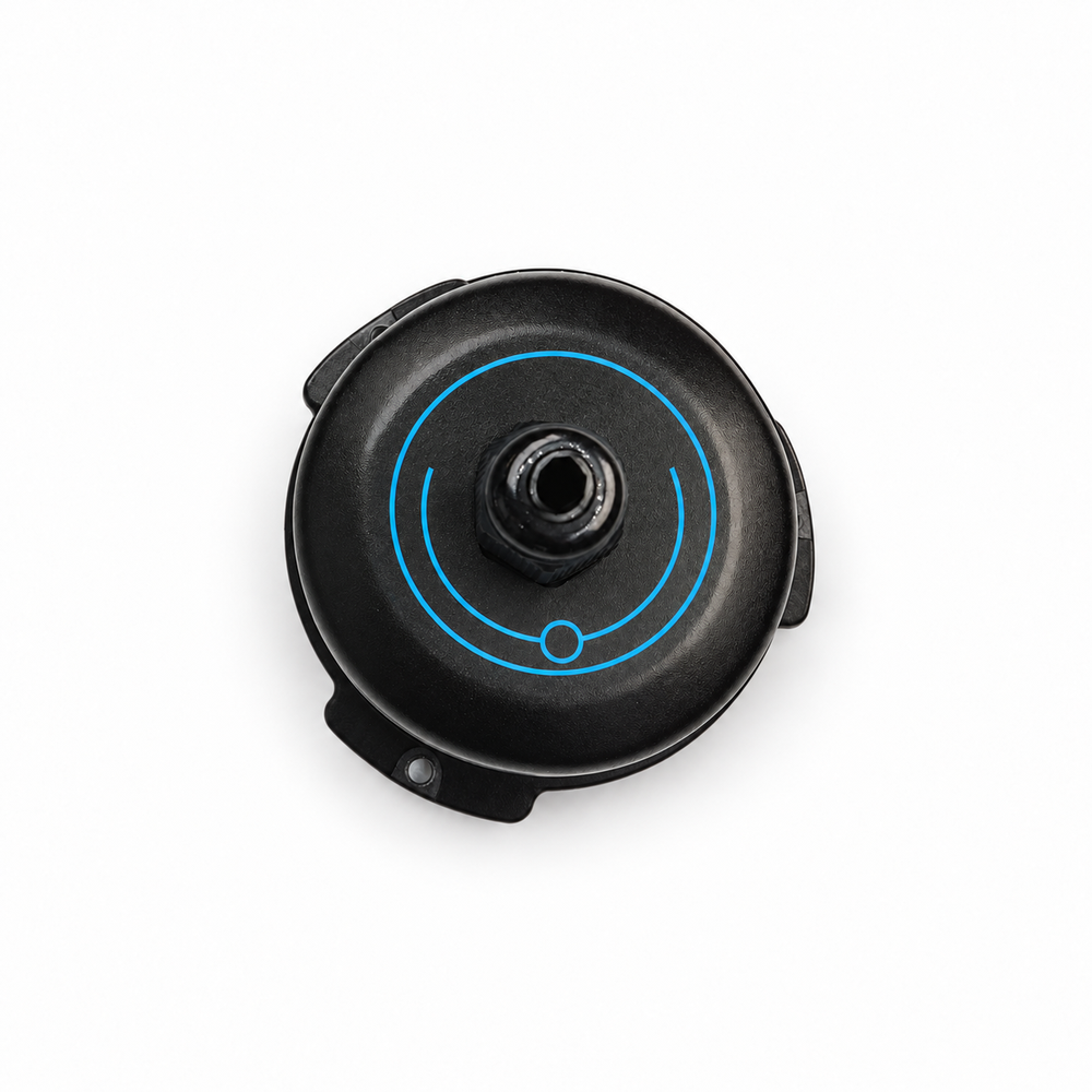
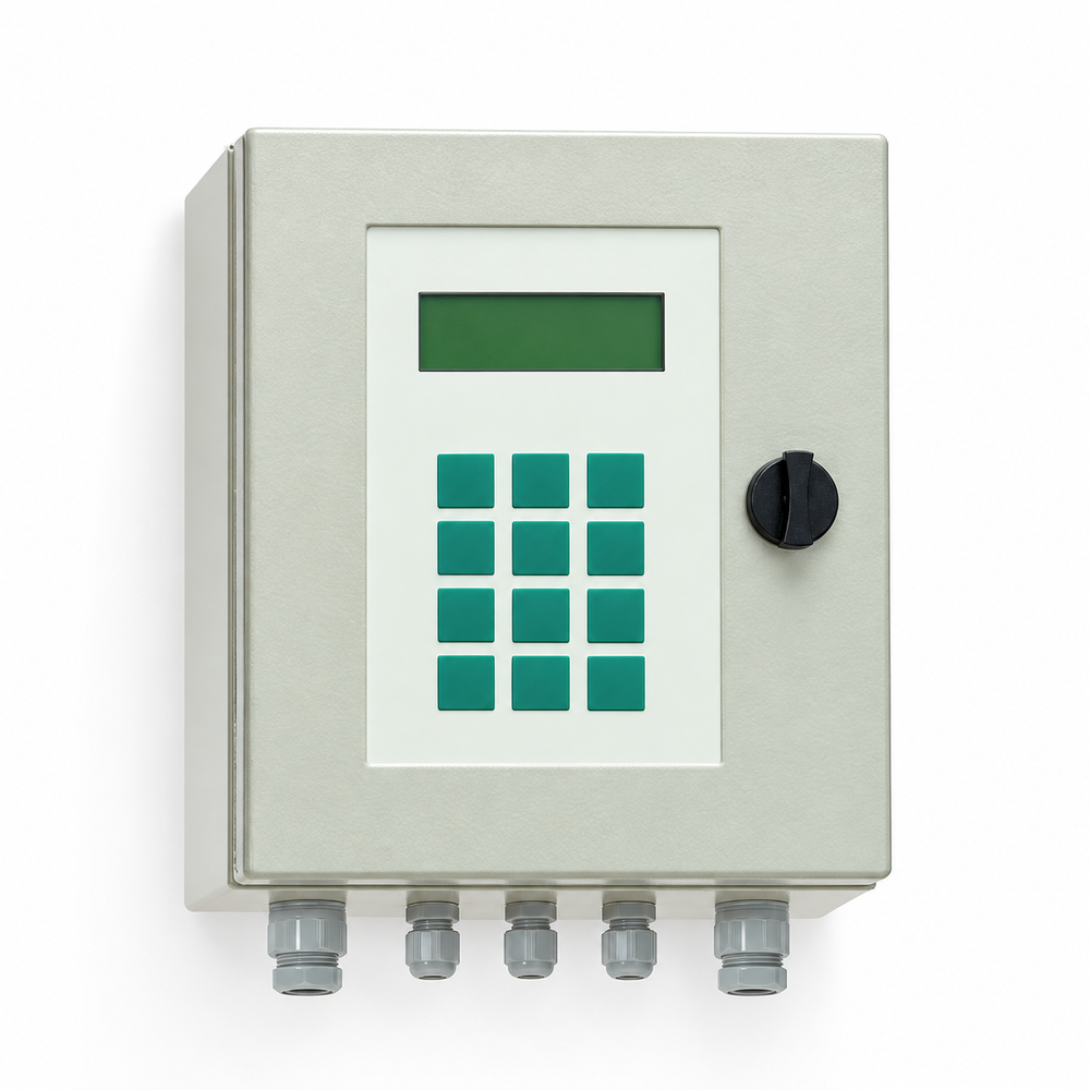
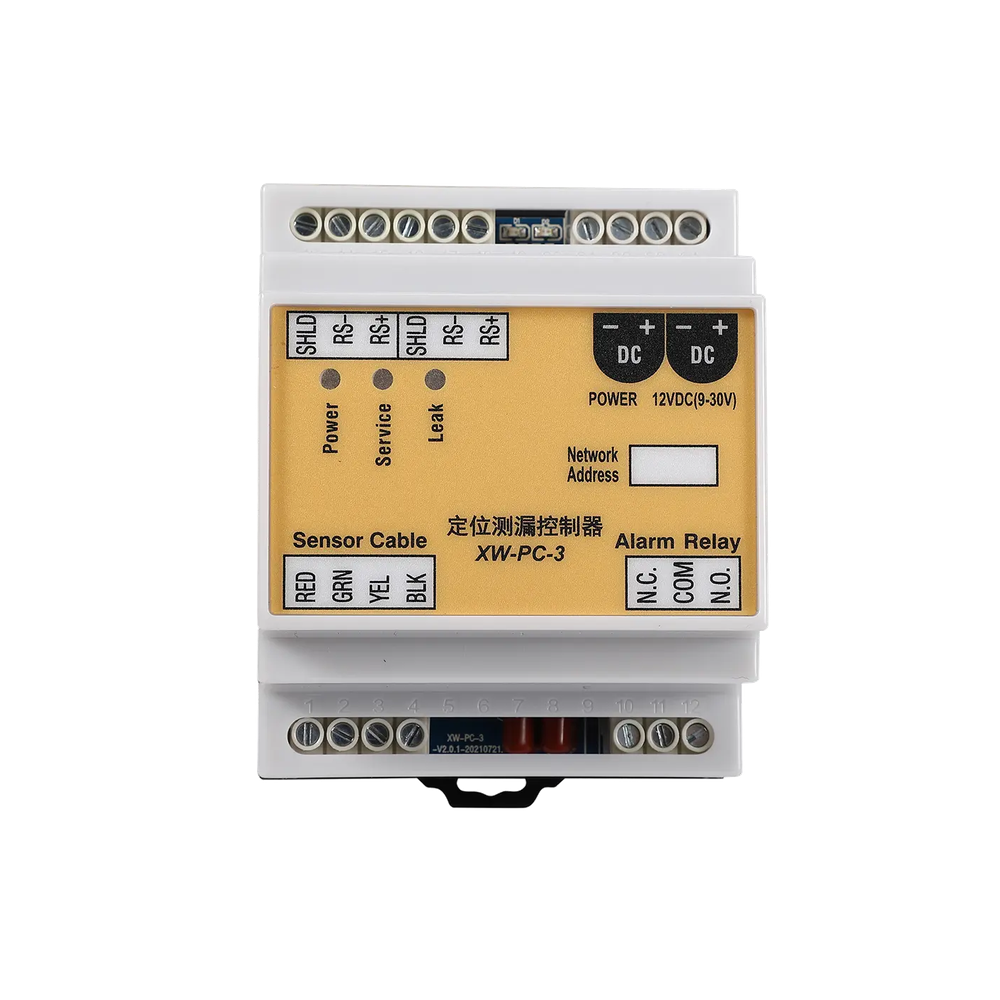
The main photo shows the XW-PC-3 controller body, cable terminals, power input and alarm relay terminals. The manufacturer lists one relay plus RS485; the connected sensing line is a separate component.
Selection
Check the cable topology and total zone length against the maker's up-to-150 m limit. Define communication protocol and alarm output integration before selecting the controller and cable as a pair.
Configuration options
Specify controller mounting, cable ends, network address, relay state and local power. The cited response time belongs to the maker's stated reference context, not a promised whole-site alarm time.
Application limits
No leak location accuracy is asserted for an arbitrary cable or coolant. The manufacturer's Chinese and English pages differ in a default bus-address detail, so the commissioning address must be checked on the actual unit.