Technical selection
Specifications and configuration
Reference — GF in-rack manifold
| Parameter | Documented value / configuration |
|---|---|
| Material | PVDF |
| Mounting | top feed; bottom feed |
| Integrated components | main connections; branch ports; quick disconnects; optional air bleed; optional drain |
| Test conditions | 100% pressure tested with water before shipment; acceptance pressure/time are not stated in the sheet and must be agreed. |
Reference — PVDF in-rack manifold / factsheet 04.26
| Parameter | Documented value / configuration |
|---|---|
| Pressure designation | PN10Conditions: limit: Nominal designation; allowable pressure depends on temperature, coolant and final assembly. Page 2 derating curve applies. |
| Temperature range | maximum: 80; minimum: -20 °CConditions: limit: Datasheet temperature limits are not a rectangular PN10 operating envelope; consult page 2 pressure-temperature curve. |
Reference — PVDF in-rack manifold / M1161 enquiry sheet
| Parameter | Documented value / configuration |
|---|---|
| Geometry rfq inputs | Maximum length, available width/depth, outer diameter, outlet count, initial port offset u0 and subsequent spacing u1; attach a drawing for non-uniform spacing.Conditions: scope: Required design inputs, not fixed catalog dimensions |
| Connection rfq inputs | Specify the exact quick-disconnect interface, nominal diameter and thread connection; listed supplier alternatives do not imply cross-brand interchangeability.Conditions: scope: Manufacturer blank enquiry form options; compatibility still requires matching interface drawings |
| Feed and service options | Top or bottom feed, straight or 90-degree feed geometry, orientation, end cap, vent or drain; define the installed routing.Conditions: scope: Custom-design inputs in the enquiry sheet; each arrangement requires drawing confirmation |
Manufacturer series reference. Confirm the exact order code, mating parts and stated conditions for the quoted configuration.
Overview
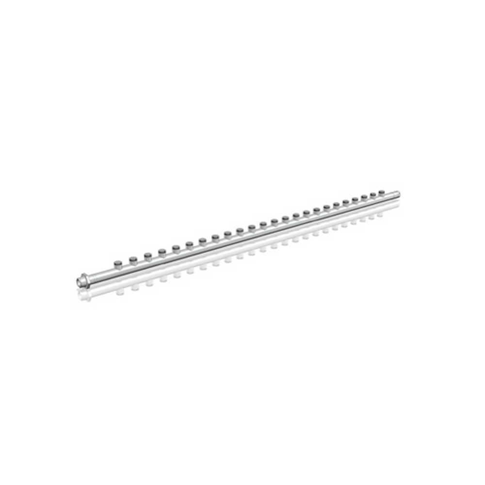
This GF PVDF in-rack manifold distributes and collects liquid across multiple server branches. It is a configured distribution component, not a complete rack cooling system, and its supply-return paths and branch positions must be designed for each installation.
Construction and interfaces
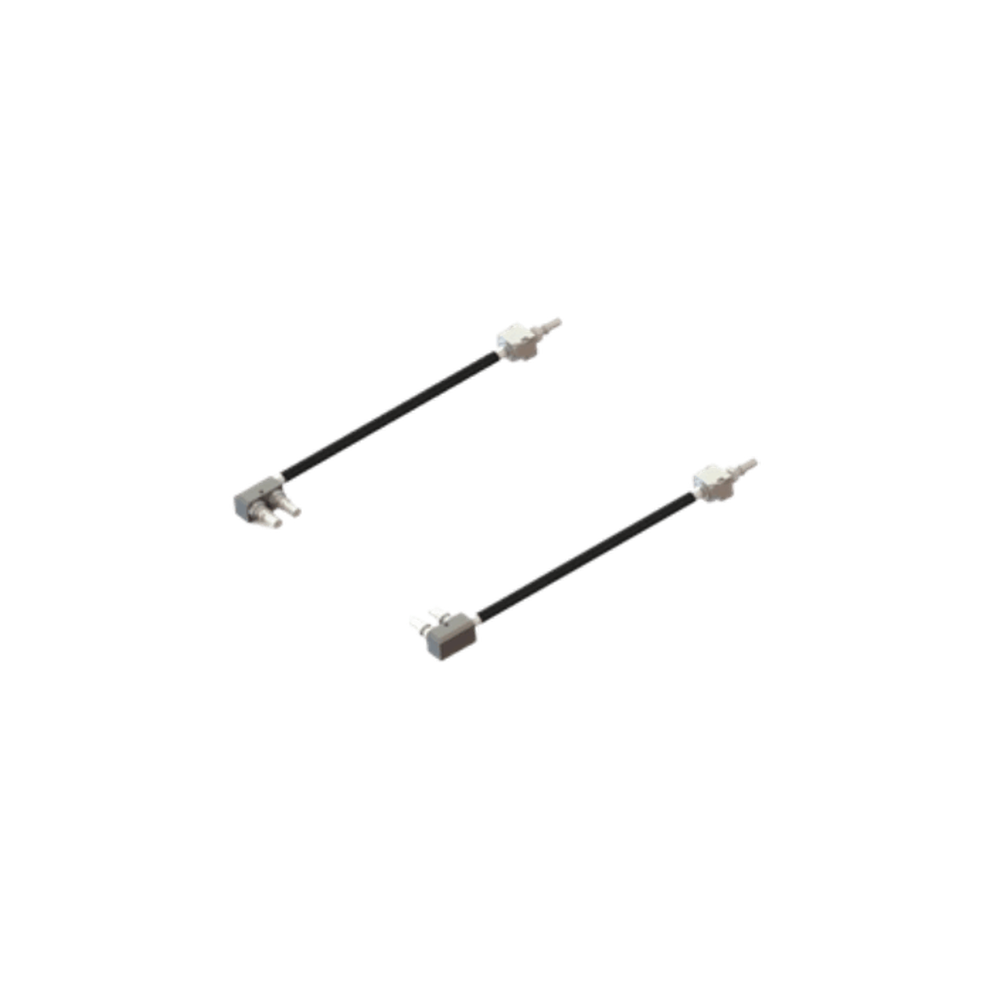
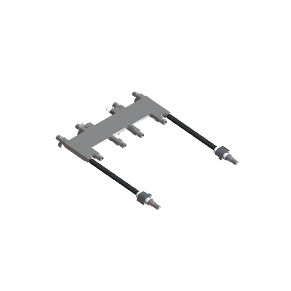
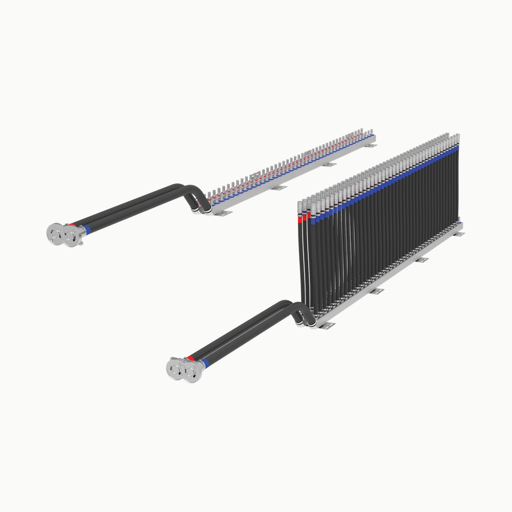
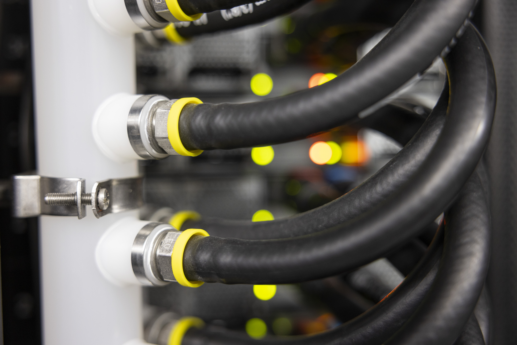
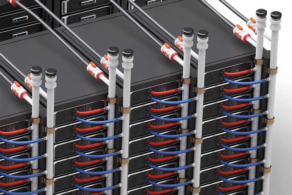
The source identifies PVDF piping with main and branch connections, optional quick disconnects and service features. The close-up photograph shows actual branch interfaces and support details; the supplementary rendering shows the installation context without fixing a standard port count.
Selection
Start from rack envelope, top or bottom feed, maximum length and available width/depth, port count and spacing, per-outlet flow and pressure-drop target. The manufacturer enquiry sheet requests exact quick-disconnect interface and a drawing for non-uniform spacing.
Configuration options
Documented options include supply/return layout, straight or 90-degree feed, end cap, vent and drain. Choose the actual branch and main connectors and verify each selected material and joining method against fluid chemistry and cleanliness requirements.
Application limits
The referenced fact sheet gives a PN10 pressure designation and a temperature span, not a universal combined duty envelope for every custom layout. A simulation example with many branches is not a standard catalogue part or proof of any proposed manifold's uniformity.