Technical selection
Specifications and configuration
Reference — PF3WB Series
| Parameter | Documented value / configuration |
|---|---|
| Construction | Integrated basic type combines supply and return in one manifold unit |
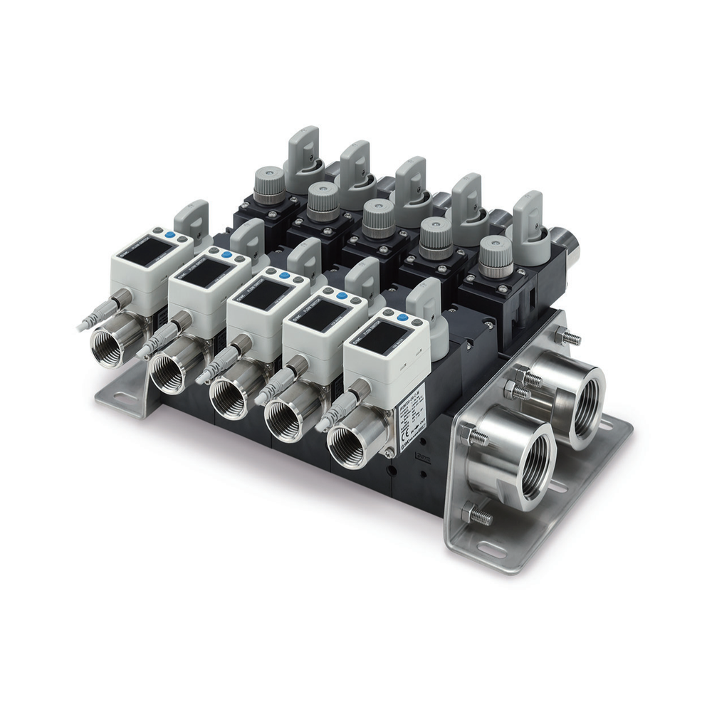
| Pictured configuration | Manufacturer photograph depicts integrated supply and return with individual flow displays and valve handles |
| Rated flow options | 0.5–4, 2–16 or 5–40 L/min per selected flow-switch unit; not the assembled manifold total flow |
| Station count options | 1–10 stations; maximum 5 stations when the selected branch flow symbol is 40 (5–40 L/min) |
| Port size options | 1 in main pipe; attachment ports 3/8, 1/2 or 3/4 in, subject to selected unit and flow passage |
| Wetted parts material | PPS, 304 stainless steel and FKM in the catalogued construction; check selected unit and fluid |
| Published fluid pressure temperature | Water or ethylene-glycol aqueous solution at viscosity ≤3 mPa·s; fluid 0–90 °C; listed operating pressure 0–1 MPa changes with fluid temperature |
| Supply return unit options | Supply: flow-adjustment or stop-valve units; return: flow-switch, flow-adjustment or stop-valve units |
| Mounting dimension basis | Front-view mounting-hole positions vary with station count n and selected branch flow-range symbol; use the order-specific dimensional drawing |
Manufacturer series reference. Confirm the exact order code, mating parts and stated conditions for the quoted configuration.
Overview
PF3WB integrates supply and return into one water-flow manifold. It suits a selected branch-monitoring circuit when a buyer wants a compact assembled arrangement rather than separately positioned headers.
Construction and interfaces
The manufacturer photograph shows multiple branch flow displays and valve handles on a single manifold body. The exact number of stations and each branch's components are order-dependent.
Selection
Choose station count, port size, flow-switch range and adjustment or stop-valve arrangement against the branch duty. The published 0.5–4, 2–16 and 5–40 L/min figures are selectable single-unit ranges, not aggregate manifold flow.
Configuration options
The catalog shows flow switches, stop valves and flow-adjustment valves as unit options. Define supply/return orientation and wiring before requesting an order-specific drawing.
Application limits
Catalog imagery is a series example, not proof of every combination. Coolant chemistry, glycol concentration, pressure drop and complete assembly ratings need confirmation for the chosen configuration.