Technical selection
Specifications and configuration
Reference — FITOK CA adjustable-cracking check valve series
| Parameter | Documented value / configuration |
|---|---|
| Documented function | Adjustable cracking-pressure check valve with spring selectionConditions: scope: Adjustment differs from fixed-cracking CV, CH and CO constructions |
| Listed adjustment envelope | 0.2 to 41.4 barConditions: scope: Manufacturer series envelope across springs, not each individual configuration's continuous adjustment range |
| Manufacturer max working pressure | up to 207 barConditions: scope: Series maximum subject to selected body, seal and temperature |
| Listed temperature span | -23 to 190 degCConditions: scope: Do not combine with the series maximum pressure without curve and configuration review |
| Listed tube end options | CASS-FL4 1/4 in and CASS-ML6, CASS-ML8, CASS-ML10 6/8/10 mm FITOK tube-fitting examples; a 1/4 in FR male end is also listedConditions: scope: Series examples; inlet and outlet end codes are selected separately |
| Listed body material | 316 stainless-steel CASS body code is shown in the CA Series ordering exampleConditions: scope: A documented stainless-steel option; no unverified universal seal or coolant statement |
Manufacturer series reference. Confirm the exact order code, mating parts and stated conditions for the quoted configuration.
Overview
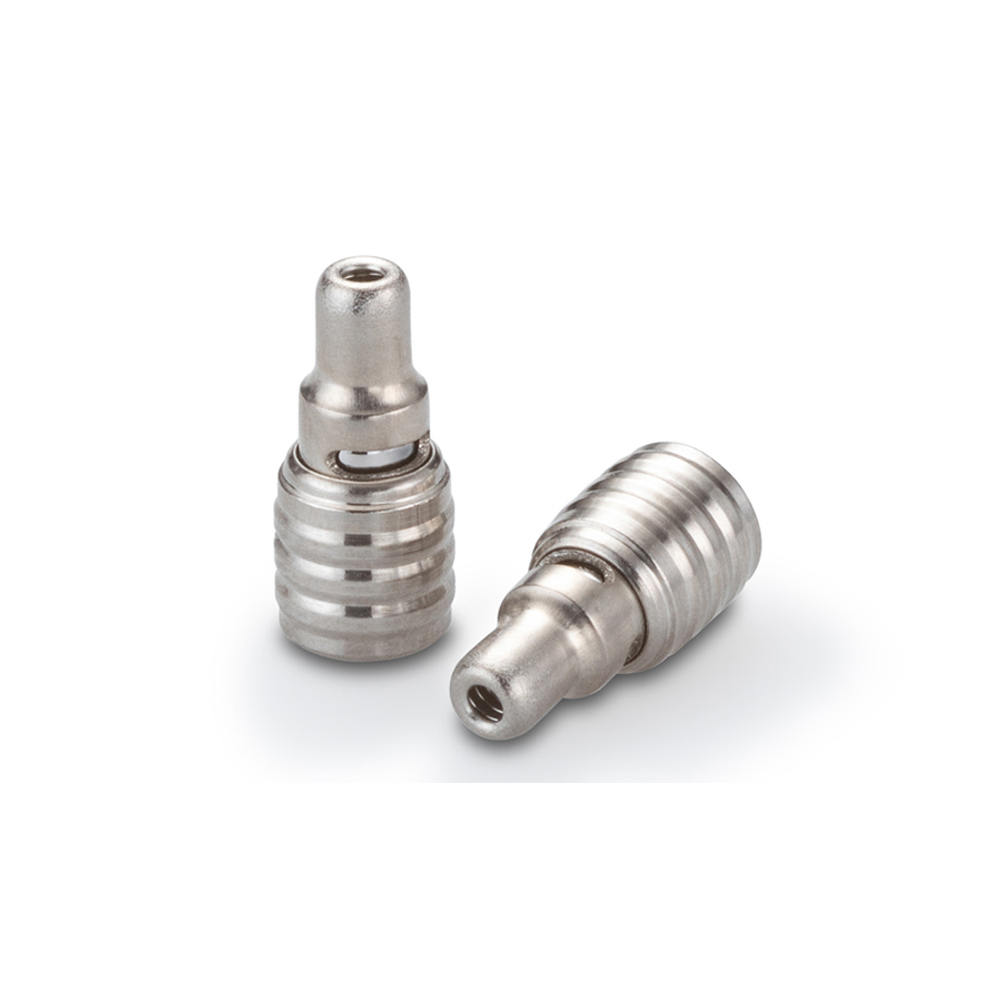
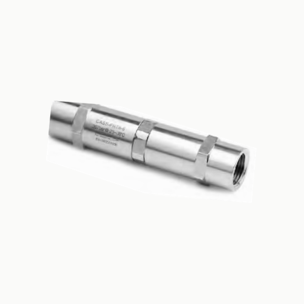
An adjustable-cracking check valve is useful when the reverse-flow barrier needs a specified opening point that cannot be selected solely by a fixed spring code. The pictured CA-style item is a reference product, not an installed performance guarantee.
Construction and interfaces
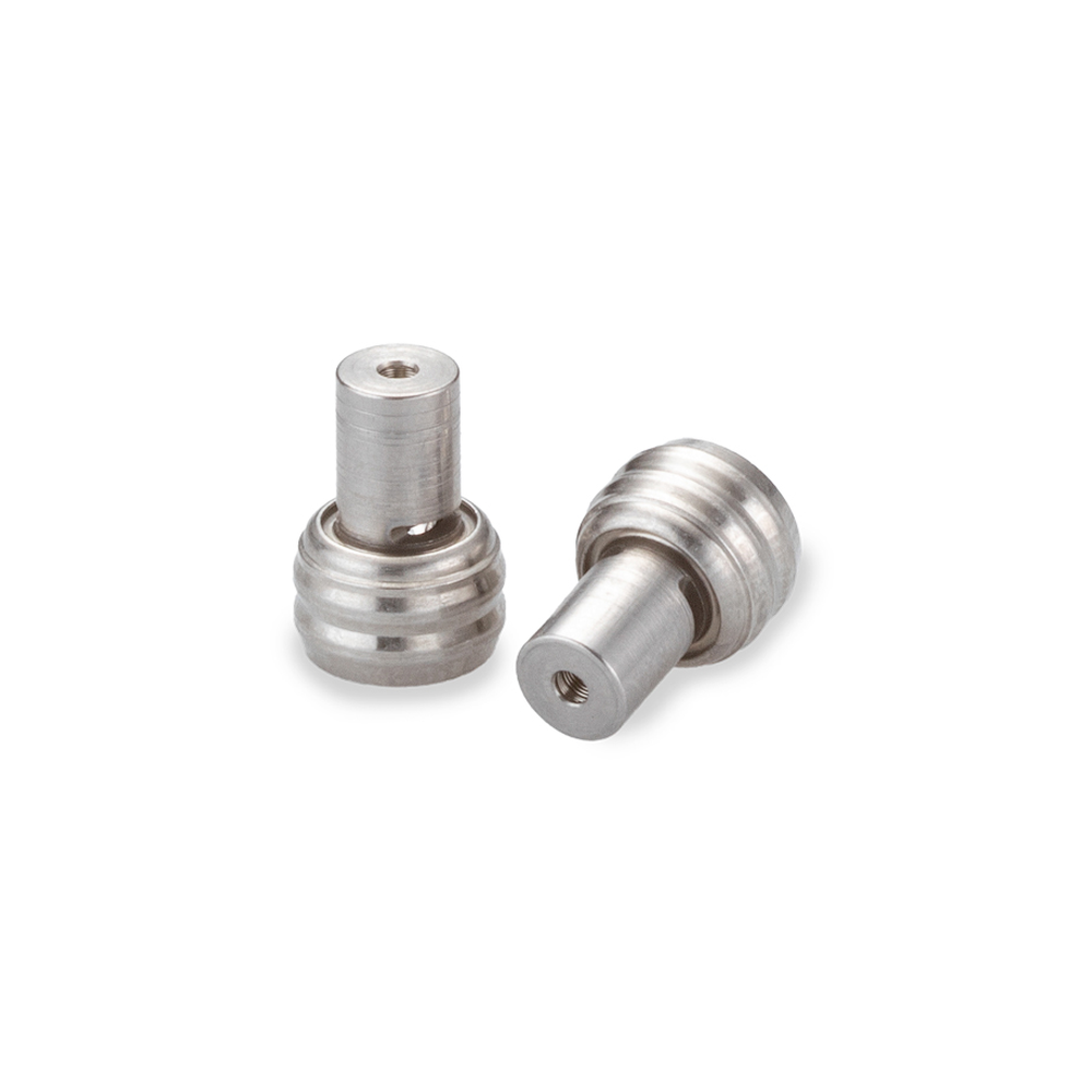
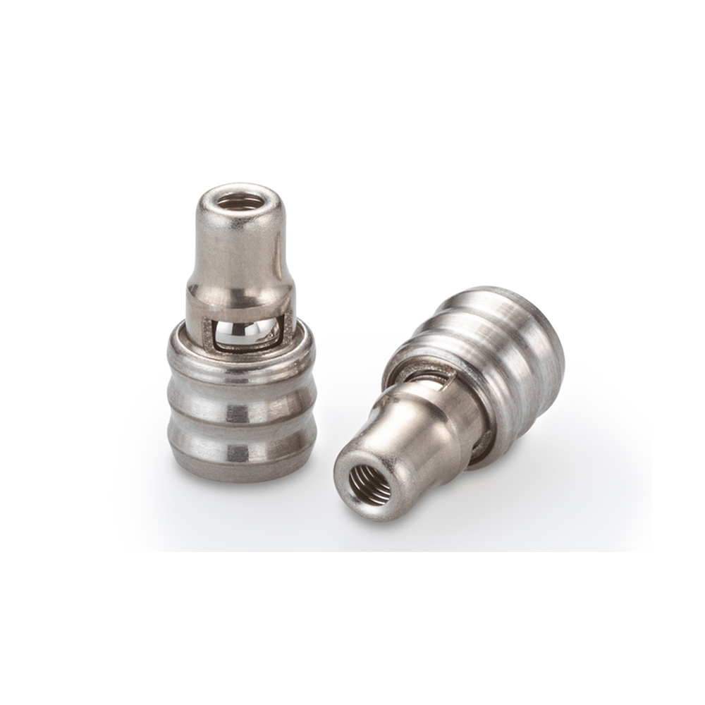
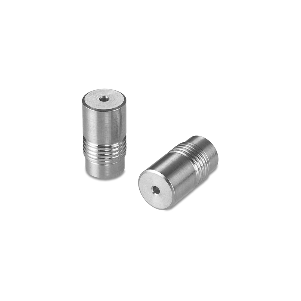
The manufacturer's CA series uses an adjustable spring mechanism in an elongated inline metal body. The photograph shows an actual CA-shaped component, while material, thread, spring and final set point require a controlled configuration and test record.
Selection
Treat the catalog adjustment envelope as the span of available spring arrangements, not as the continuous adjustment range of every assembled valve. Set the desired cracking point and verify opening and resealing at the specified fluid condition.
Configuration options
Specify body and seal materials, both end standards, adjustment range and tamper or set-point documentation. Spring choices and connection forms are catalog options, not a promise that the pictured configuration includes each one.
Application limits
An adjustable check valve is not a proportional relief valve or regulator. The reference pressure and temperature limits require material and selected configuration review, and no coolant compatibility or site acceptance certificate is inferred.