Technical selection
Specifications and configuration
Reference — Liquid Cooling Assemblies (March 2026)
| Parameter | Documented value / configuration |
|---|---|
| Material | Stainless steelConditions: scope: Tube-series description; grade not specified |
| Forming options | CNC-bent one-piece tubing; custom Y assemblies and manifoldsConditions: limits: No fixed OD, wall thickness or tolerance given; do not infer from photo |
| Custom end fitting options | MFC lists custom end fitting configurations and custom flaring/parflange as formed-tube capabilities; the photographed Y assembly's actual end preparation is not identified.Conditions: scope: Capability choices for a drawing-defined order, not a claim about the pictured sample's ends |
| Pipe tube joining options | MFC lists pipe and tube welding and brazing as capabilities; the pictured Y assembly's joint method requires a controlled drawing.Conditions: scope: Family capability, not an identified weld or braze on the pictured Y assembly |
Manufacturer reference configuration. Values and conditions apply to the named reference; the supplied configuration requires separate confirmation.
Overview
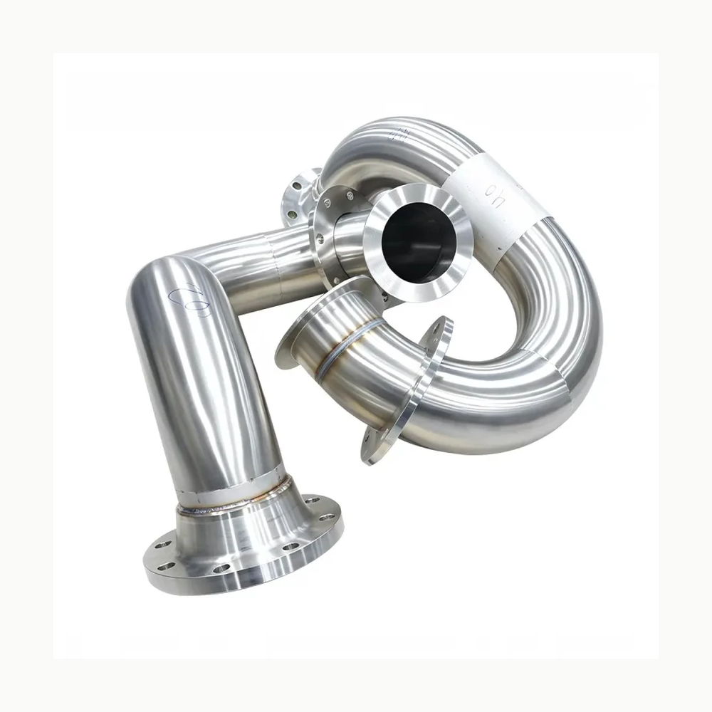
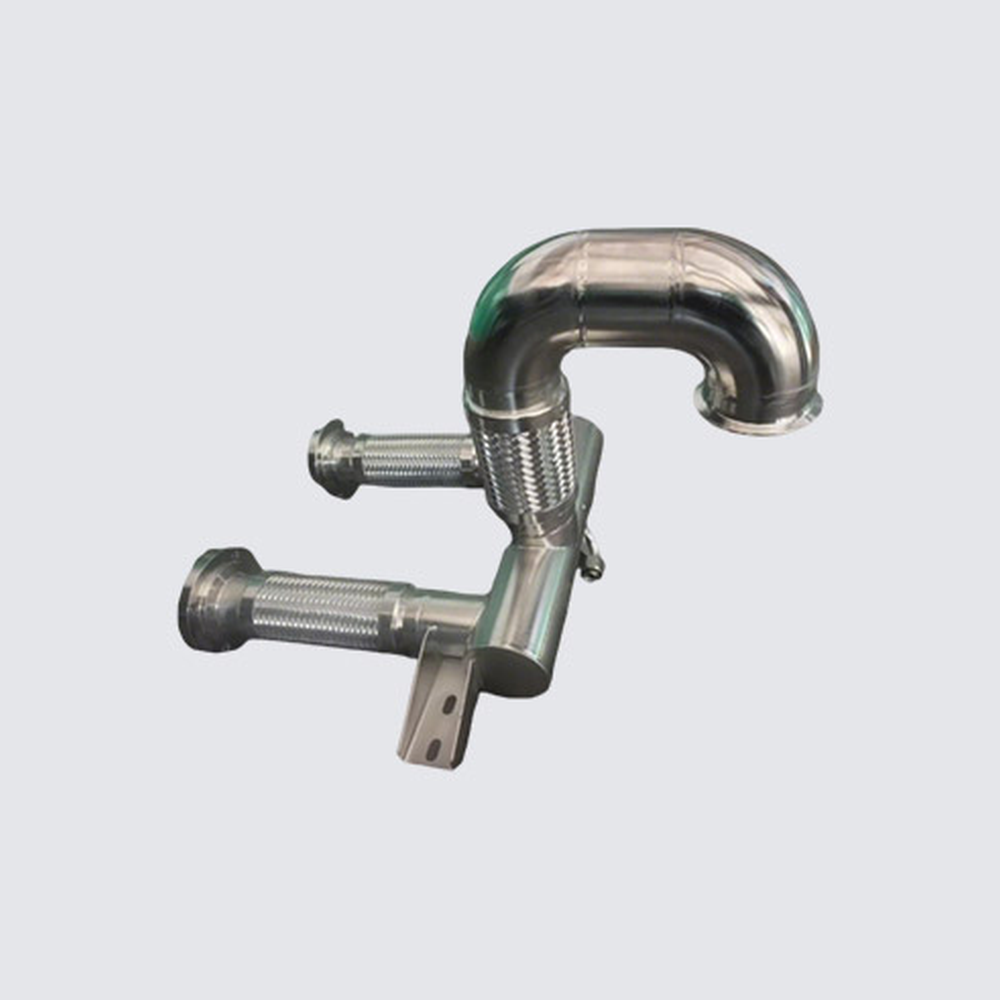
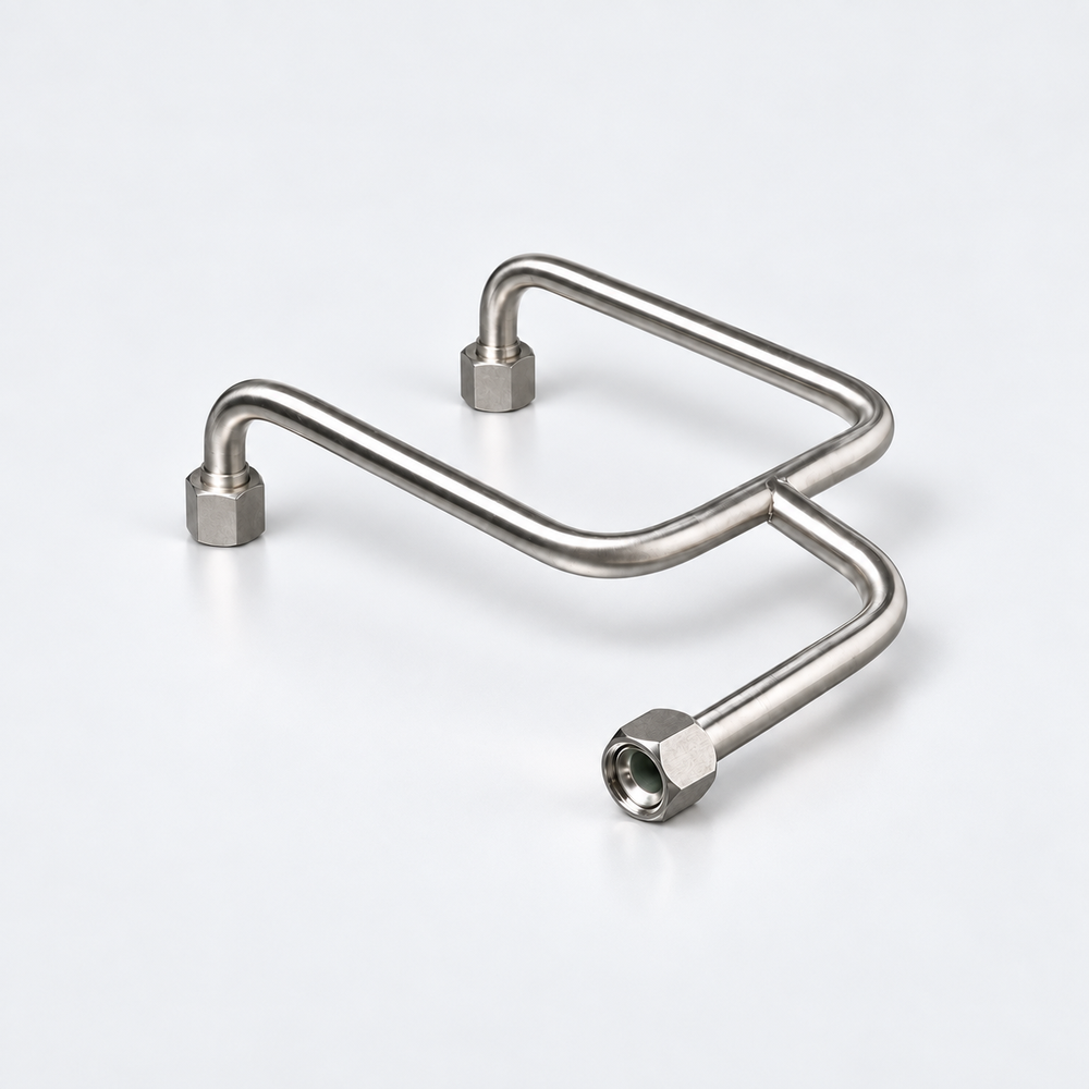
This photographed formed Y-tube is a drawing-defined stainless component for routing coolant through three controlled ends. It is a real manufacturer assembly example rather than a catalog part number; the branch geometry and end orientation are the purchasing identity of the illustrated configuration.
Construction and interfaces
The photo shows one branched, multiple-bend metal tube assembly with three threaded or nut-style end components. The manufacturer describes robotic CNC tube forming and one-piece bends to reduce additional joining fittings. The photo cannot establish its tube OD, wall, weld method or exact end standard.
Selection
Start from the mating equipment locations and installation datums, then specify branch position, tube route, bend radii, clearance, end orientation and assembly-level dimensional tolerance. A similar-looking tube with different end angles may not fit the rack or cold-plate connection.
Configuration options
MFC identifies custom end fittings, flaring/parflange, and pipe or tube welding/brazing as formed-tube capabilities. These are drawing-defined alternatives; the photo does not establish which end preparation or joint was used on this Y assembly. Material grade, tube OD and wall, branch geometry, cleaning and inspection are also controlled design inputs, not preset dimensions on the pictured unit.
Application limits
Neither the sheet nor image provides a fixed model number, measured dimensions, pressure/temperature rating, coolant approval or certification for this exact assembly. Do not copy hose ratings or other vendor tube-stock dimensions into this configuration. Any substitution needs an approved drawing revision and fit review.