Product family

Tube Assemblies

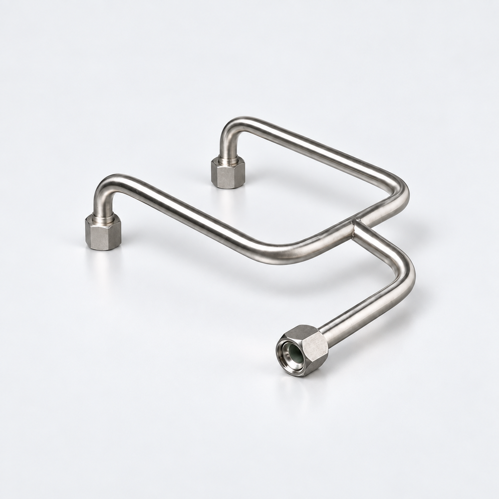
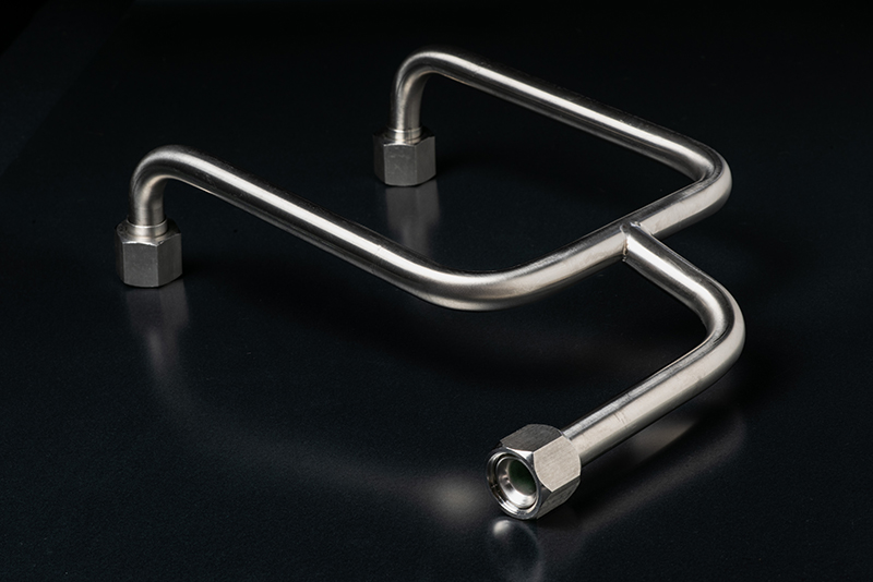
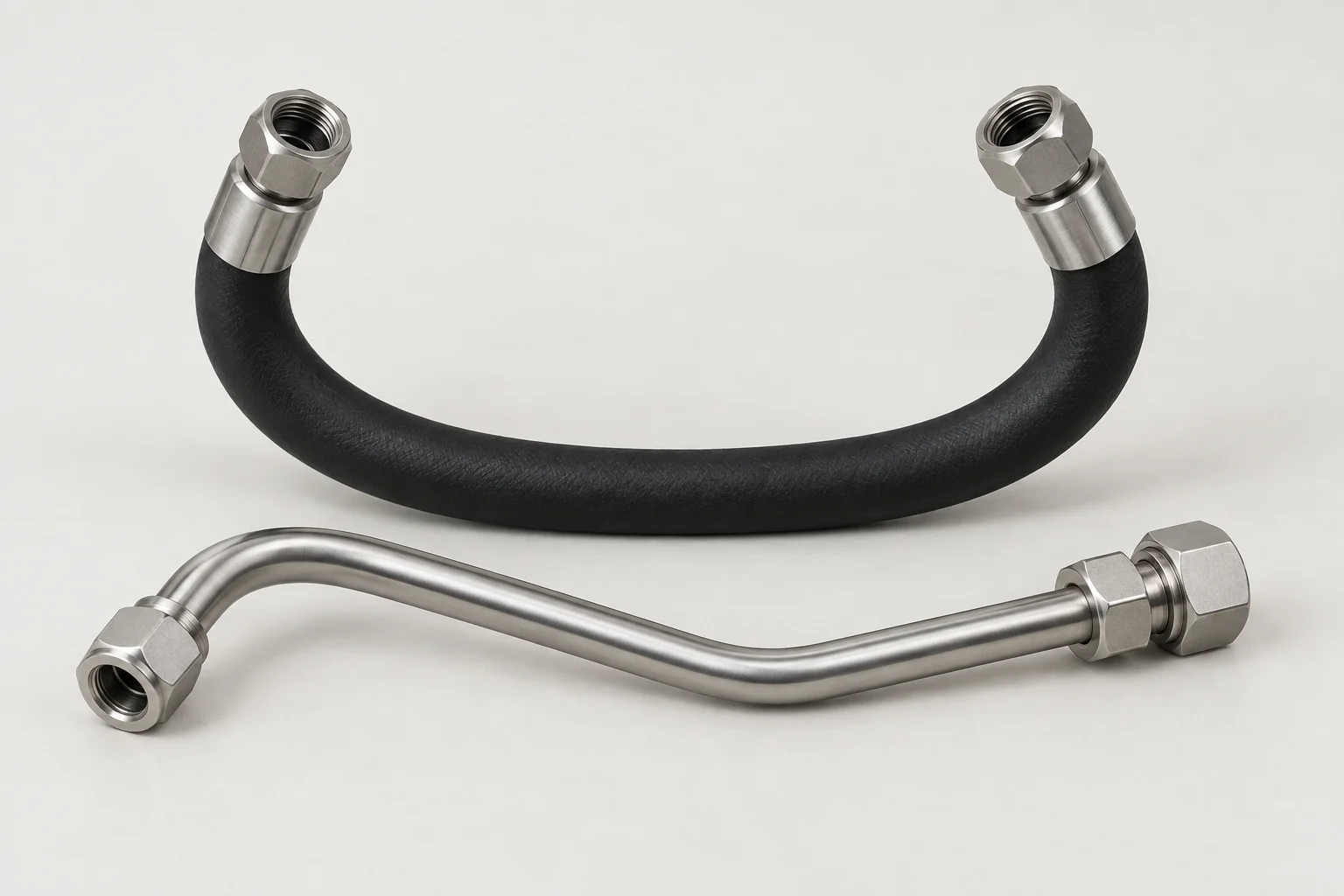
Formed rigid or semi-rigid tube assemblies with controlled routing and end geometry.

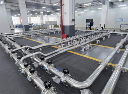
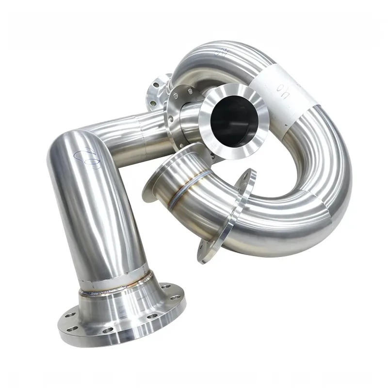
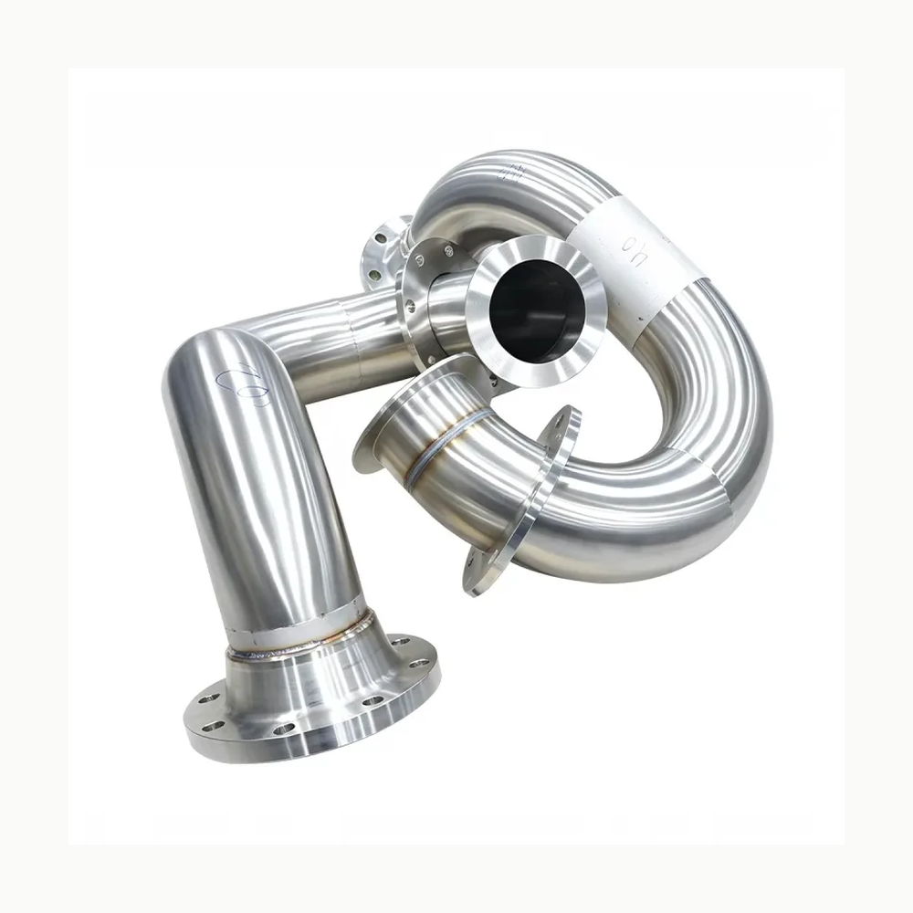
AODSON pictured set of custom 304 stainless CDU pipe assembly geometries with bends and flanged ends.
Representative component · configuration-specific

Component selection

All Product drafts

4 results
Private preview · candidate records

4 local draft records. Includes unfinished records and Family overviews. Draft · Noindex. Reference configurations are not approved stock. Image public-use review remains separate.

Show content-ready drafts
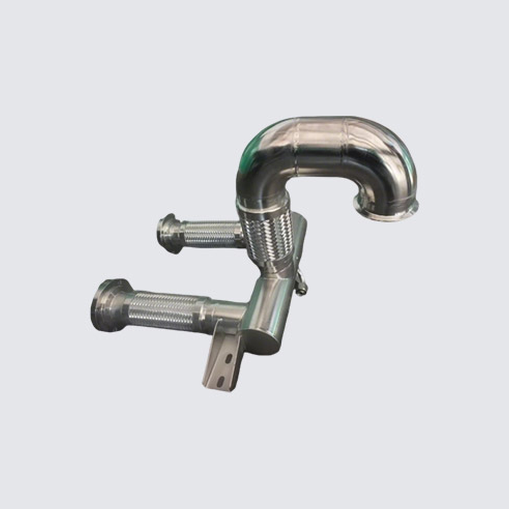
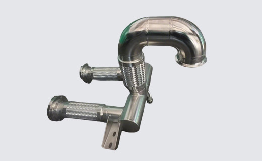
Deya formed metal system-pipe module with a return bend, flexible branches and a mounting lug; drawing-defined reference.

LCP-000072

Formed System-Pipe Module with Flexible Branches — Deya Reference

A standalone custom pipe module photograph shows a large return bend, two flexible branches and a mounting feature. The manufacturer's stainless system-pipe…

System pipe construction
Custom stainless system-pipe assemblies can use tube forming, joining and surface treatment for project-specific…
Custom order basis
The manufacturer offers drawing-based stainless system-pipe production and assembly
View specifications

Specify with confidence

The details that shape your selection.

Tube material, outside diameter, wall and surface requirements Bend drawing, datum scheme, end geometry and tolerances Connection or joining requirements and mounting points Coolant, pressure, temperature and routing envelope Cleanliness, leak-test criteria, packaging and quantity

  • Function and loop position
  • Interfaces, drawing revisions and envelope
  • Coolant, materials and seals
  • Temperature, pressure and flow conditions
  • Testing and documentation
  • Quantities and delivery requirements

Overview

Formed tube assemblies suit controlled routes where end geometry and mounting positions must repeat. Material, outside diameter, wall and bends are drawing-level choices.

Configuration and selection

Provide the controlled drawing, datum scheme, bend geometry, end forms, joining details and tolerances. Define coolant conditions, cleanliness and dimensional or leak-test acceptance.

Information to prepare

  • Tube material, outside diameter, wall and surface requirements
  • Bend drawing, datum scheme, end geometry and tolerances
  • Connection or joining requirements and mounting points
  • Coolant, pressure, temperature and routing envelope
  • Cleanliness, leak-test criteria, packaging and quantity

Configuration and quotation

Include the drawing or specification revision and identify any requirements that are still to be confirmed. Available configurations, testing and documentation are confirmed with quotation.

Documented reference configurations & supporting imagery

Local editorial preview

Documented configurations and product references

Manufacturer examples retain their model and conditions. These references describe source products, not approved stock or supply. Images are pending final selection and rights review.

Parker Hannifin — family reference

ParameterDocumented value / configuration
Materialadvanced polyethylene; low-density polyethylene; FEP; PTFE

Parker Hannifin — Parker Legris Advanced PE

ParameterDocumented value / configuration
MaterialAdvanced polyethylene

Parker Hannifin — Advanced PE

ParameterDocumented value / configuration
Outside diameter4, 6, 8, 10, 12 mm; 1/4, 3/8, 1/2 in
WallPart-size-specific; documented examples range from 0.75 to 1.50 mm for metric sizes.

MFC — Liquid Cooling Assemblies (March 2026)

ParameterDocumented value / configuration
MaterialStainless steelConditions: Drawing-defined tube assemblies; scope: Tube-series description; grade not specified
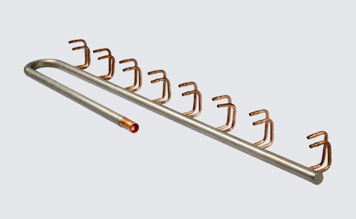
Forming optionsCNC-bent one-piece tubing; custom Y assemblies and manifoldsConditions: Drawing-defined tube assemblies; limits: No fixed OD, wall thickness or tolerance given; do not infer from photo
Custom end fitting optionsMFC lists custom end fitting configurations and custom flaring/parflange as formed-tube capabilities; the photographed Y assembly's actual end preparation is not identified.Conditions: scope: Capability choices for a drawing-defined order, not a claim about the pictured sample's ends
Pipe tube joining optionsMFC lists pipe and tube welding and brazing as capabilities; the pictured Y assembly's joint method requires a controlled drawing.Conditions: scope: Family capability, not an identified weld or braze on the pictured Y assembly

AODSON Metal — AODSON custom 304 stainless CDU pipe assembly example

ParameterDocumented value / configuration
Assembly typeDrawing-defined CDU liquid-cooling pipe and loop assemblyConditions: scope: Photographed group is representative, not one fixed stocked geometry
Listed material304 stainless steel tubing with machined flange componentsConditions: scope: Listed for pictured examples; actual wetted BOM to follow approved drawing
ConstructionFormed straight and curved tube sections with welded and machined flange interfacesConditions: scope: No fixed tube OD, wall, flange standard or finished pressure rating on the page
Configuration optionsU-loops, return bends, offset spools, branches, manifold connections, equipment risers; project-specific end connectionsConditions: scope: Options are drawing-driven and not certified interchangeable standard models
Inspection optionsDimensional inspection, weld examination, pressure or leak testing, cleanliness verification and documentation as specifiedConditions: scope: Optional inspection scope requires project acceptance criteria; not a blanket completion claim

Deya — Deya pictured custom bent pipe module type

ParameterDocumented value / configuration
System pipe constructionCustom stainless system-pipe assemblies can use tube forming, joining and surface treatment for project-specific liquid-line routingConditions: scope: Category-level method, not a fixed construction for every pictured component
Custom order basisThe manufacturer offers drawing-based stainless system-pipe production and assemblyConditions: scope: No public per-example wall thickness, pressure rating, dimensions or test result
Pictured branch and end geometryThe maker's pictured module combines one curved rigid main tube and two short braided flexible branches; the visible ends differ, and no thread or fitting standard is legibleConditions: scope: Visual form only; not measured diameter, material grade, end standard or pressure rating
Pictured mounting tabOne metal support tab with two visible mounting holes extends from the pictured rigid sectionConditions: scope: Visual mounting feature only; hole dimensions and allowable loads are not established

Configuration options and selection inputs

End form

Tube material and end-connection system must be selected as one compatible configuration.

Reference: Parker Hannifin — family reference

Joining

Push-in, cartridge, and coupling interfaces are distinct joining approaches; exact tube preparation requirements remain model-specific.

Reference: Parker Hannifin — family reference

Bend geometry

Minimum bend radius is OD- and temperature-specific; formed assemblies also require a controlled route and bend orientation.

Reference: Parker Hannifin — family reference

Datums

RFQ drawing should establish installation datums and dimensional requirements before bending/fabrication.

Reference: Swagelok Northern California — family reference

Conditions: inference: derived from CAD drawing and dimensional-requirement workflow

End form

End preparation and connection type must be controlled on the approved assembly drawing.

Reference: Swagelok Northern California — family reference

Joining

tube fitting; swaging; welding

Reference: Swagelok Northern California — family reference

Surface

Surface and material-finish requirements are project inputs; no finish may be inferred from a generic assembly service.

Reference: Swagelok Northern California — family reference

Cleanliness

Specify cleaning, capping/bagging and contamination limits; the cited workflow cleans and caps or bags completed assemblies.

Reference: Swagelok Northern California — family reference

Dimensional tolerance

Preserve OD, wall, ovality and route tolerances with the exact material/size; do not infer assembly tolerance from stock-tube tolerance.

Reference: Parker Hannifin — family reference