Technical selection
Specifications and configuration
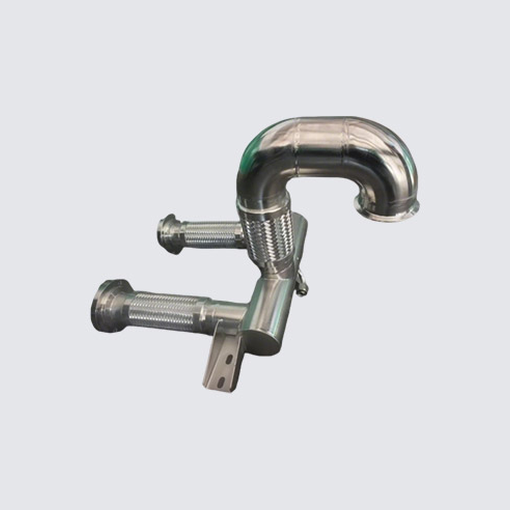
Reference — Deya pictured custom bent pipe module type
| Parameter | Documented value / configuration |
|---|---|
| System pipe construction | Custom stainless system-pipe assemblies can use tube forming, joining and surface treatment for project-specific liquid-line routingConditions: scope: Category-level method, not a fixed construction for every pictured component |
| Custom order basis | The manufacturer offers drawing-based stainless system-pipe production and assemblyConditions: scope: No public per-example wall thickness, pressure rating, dimensions or test result |
| Pictured branch and end geometry | The maker's pictured module combines one curved rigid main tube and two short braided flexible branches; the visible ends differ, and no thread or fitting standard is legibleConditions: scope: Visual form only; not measured diameter, material grade, end standard or pressure rating |
| Pictured mounting tab | One metal support tab with two visible mounting holes extends from the pictured rigid sectionConditions: scope: Visual mounting feature only; hole dimensions and allowable loads are not established |
Manufacturer series reference. Confirm the exact order code, mating parts and stated conditions for the quoted configuration.
Overview
This mixed rigid-and-flexible pipe module routes fluid around a compact return bend while presenting branch interfaces. It is a real photographed form, not a universal drawing or fixed-size stock part.
Construction and interfaces
The visible example combines a bent main pipe, two flexible branch sections and a support lug. The manufacturer's system-pipe category describes formed and joined stainless piping supplied to a project design.
Selection
Check the installed envelope, bend radius, flexible-branch orientation and support points on the mating equipment. Include thermal movement and assembly access in the drawing review.
Configuration options
Route geometry, tube size and wall, branch-end style, flexible-section length, joining process and mounting interface can be specified by the project drawing and manufacturing review.
Application limits
The photo alone cannot verify the exact alloy, reinforcement, pressure, flow or leak performance. These must be established for the approved bill of materials and tested final assembly.