Technical selection
Specifications and configuration
Reference — PF3WC Series
| Parameter | Documented value / configuration |
|---|---|
| Construction | Integrated straight type combines supply and return in one unit with supply and return piping arranged in the same direction |
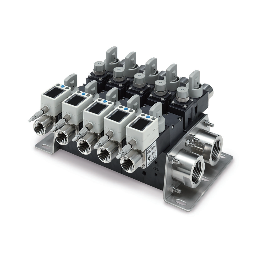
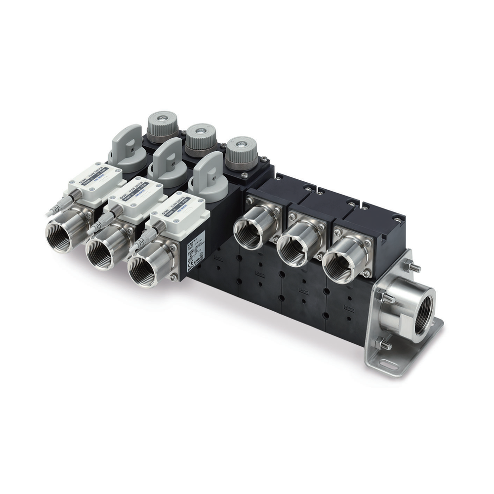
| Pictured configuration | Manufacturer photograph depicts straight-layout unit with flow-sensing and valve stations |
| Rated flow options | 0.5–4, 2–16 or 5–40 L/min per selected flow-switch unit; not a whole-manifold rating |
| Station count options | Supply 1–5 stations and return 1–5 stations |
| Port size options | 1 in main pipe; attachment ports 3/8, 1/2 or 3/4 in, subject to selected unit and flow passage |
| Wetted parts material | PPS, 304 stainless steel and FKM in the catalogued construction; check selected unit and fluid |
| Published fluid pressure temperature | Water or ethylene-glycol aqueous solution at viscosity ≤3 mPa·s; fluid 0–90 °C; listed operating pressure 0–1 MPa changes with fluid temperature |
| Supply return unit options | Supply: flow-adjustment or stop-valve units; return: flow-switch, flow-adjustment or stop-valve units |
| Mounting dimension basis | Straight-type mounting-hole positions vary with station count n and selected branch flow-range symbol; use the order-specific dimensional drawing |
Manufacturer series reference. Confirm the exact order code, mating parts and stated conditions for the quoted configuration.
Overview
PF3WC keeps supply and return in one assembly but changes the connection layout: both main piping directions are arranged on the same side. This is a routing difference from the basic PF3WB configuration.
Construction and interfaces
The manufacturer photograph shows a straight-layout body with separate branch connections, flow-sensing stations and valve stations. It does not identify one fixed station count or full order code.
Selection
Check the same-direction pipe clearance and the individual branch duties. Select the catalog's 0.5–4, 2–16 or 5–40 L/min flow-switch option per branch; these are not whole-manifold flow ratings.
Configuration options
Specify the number and makeup of branch stations, stop/adjustment valves, sensing and display or signal requirements. Confirm the exact port and mounting arrangement with the manufacturer drawing.
Application limits
No pressure, total-flow or pressure-drop guarantee is inferred from the photograph. Fluid compatibility and permissible envelope belong to the selected variant and actual circuit conditions.