Technical selection
Specifications and configuration
Reference — PF3WR Series
| Parameter | Documented value / configuration |
|---|---|
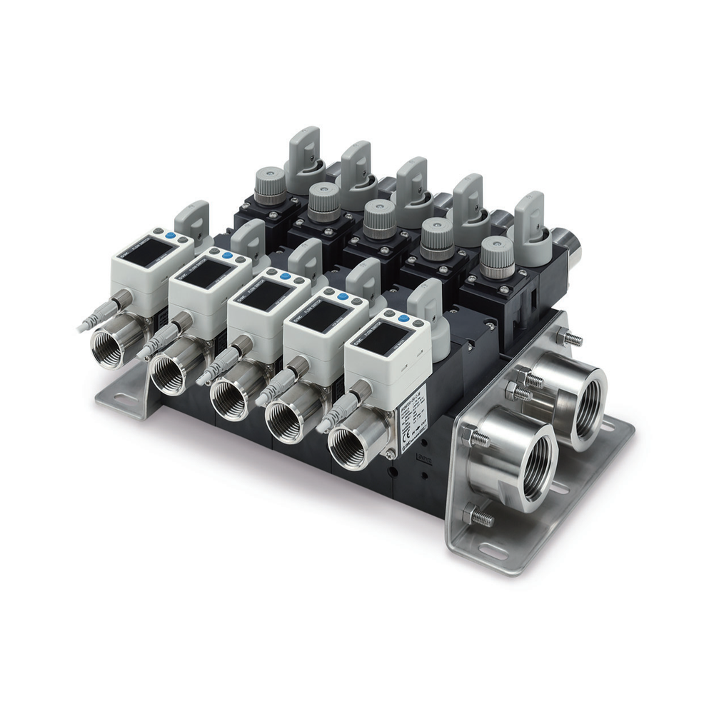
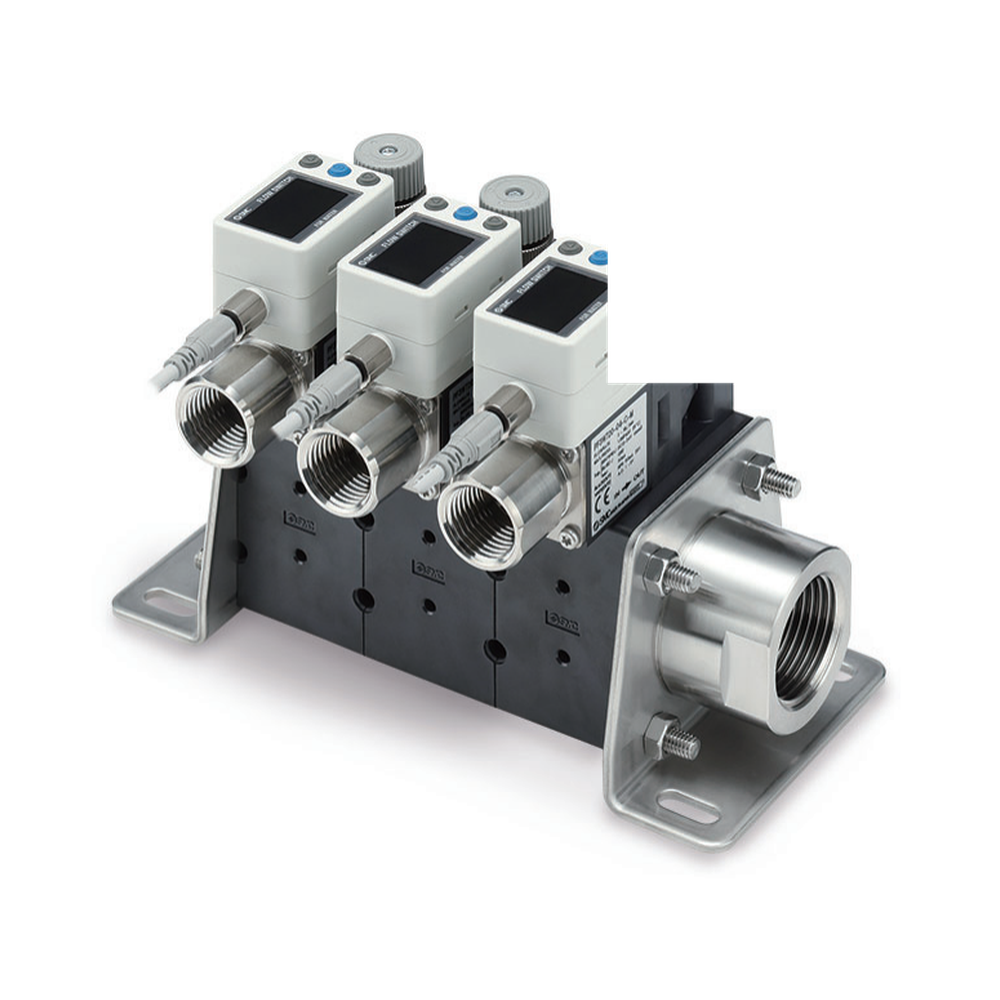
| Construction | Remote-type return manifold separated from the supply unit; pictured with individual digital flow displays |
| Pictured configuration | Manufacturer photograph shows return manifold stations with digital flow-sensing modules |
| Fluid context | Catalog depicts use with water or ethylene-glycol aqueous solution, fluid temperature 0–90 °C under catalog conditions |
| Station count options | 1–10 return stations; maximum 5 stations when selected branch flow symbol is 40 (5–40 L/min) |
| Port size options | 1 in main pipe; attachment ports 3/8, 1/2 or 3/4 in, subject to selected unit and flow passage |
| Wetted parts material | PPS, 304 stainless steel and FKM in the catalogued construction; check selected unit and fluid |
| Published fluid pressure temperature | Water or ethylene-glycol aqueous solution at viscosity ≤3 mPa·s; fluid 0–90 °C; listed operating pressure 0–1 MPa changes with fluid temperature |
| Return unit options | Return side selects flow-switch, flow-adjustment and stop-valve units; IO-Link is limited to compatible integrated-display flow-switch options |
| Mounting dimension basis | Remote return-unit mounting-hole positions vary with station count n and branch flow-range symbol; use the order-specific dimensional drawing |
Manufacturer series reference. Confirm the exact order code, mating parts and stated conditions for the quoted configuration.
Overview
PF3WR is a separate return-side manifold with branch flow-switch stations. It is a distinct purchasing object from the valve-only PF3WS supply unit and from the integrated PF3WB/PF3WC layouts.
Construction and interfaces
The manufacturer photograph identifies PF3WR Return type and shows three individual digital flow displays. Station count and sensor selection vary by ordered configuration.
Selection
Pair with the intended supply arrangement and select each return branch's flow range and monitoring output. The catalog depicts water and ethylene-glycol aqueous service at 0–90 °C under stated conditions.
Configuration options
Specify branch count, sensing range, electrical output, main connection and mounting. Stop or adjustment valve choices require an order-specific review of the return-unit station configuration.
Application limits
The pictured displays cannot prove a selected order code, total-flow capacity or fluid compatibility for any glycol mixture. Confirm exact viscosity, pressure, temperature and electrical conditions before quotation.