Product family

Rack Manifolds & Distribution Assemblies

Rack and loop distribution components configured around port layout, mounting, and flow requirements.

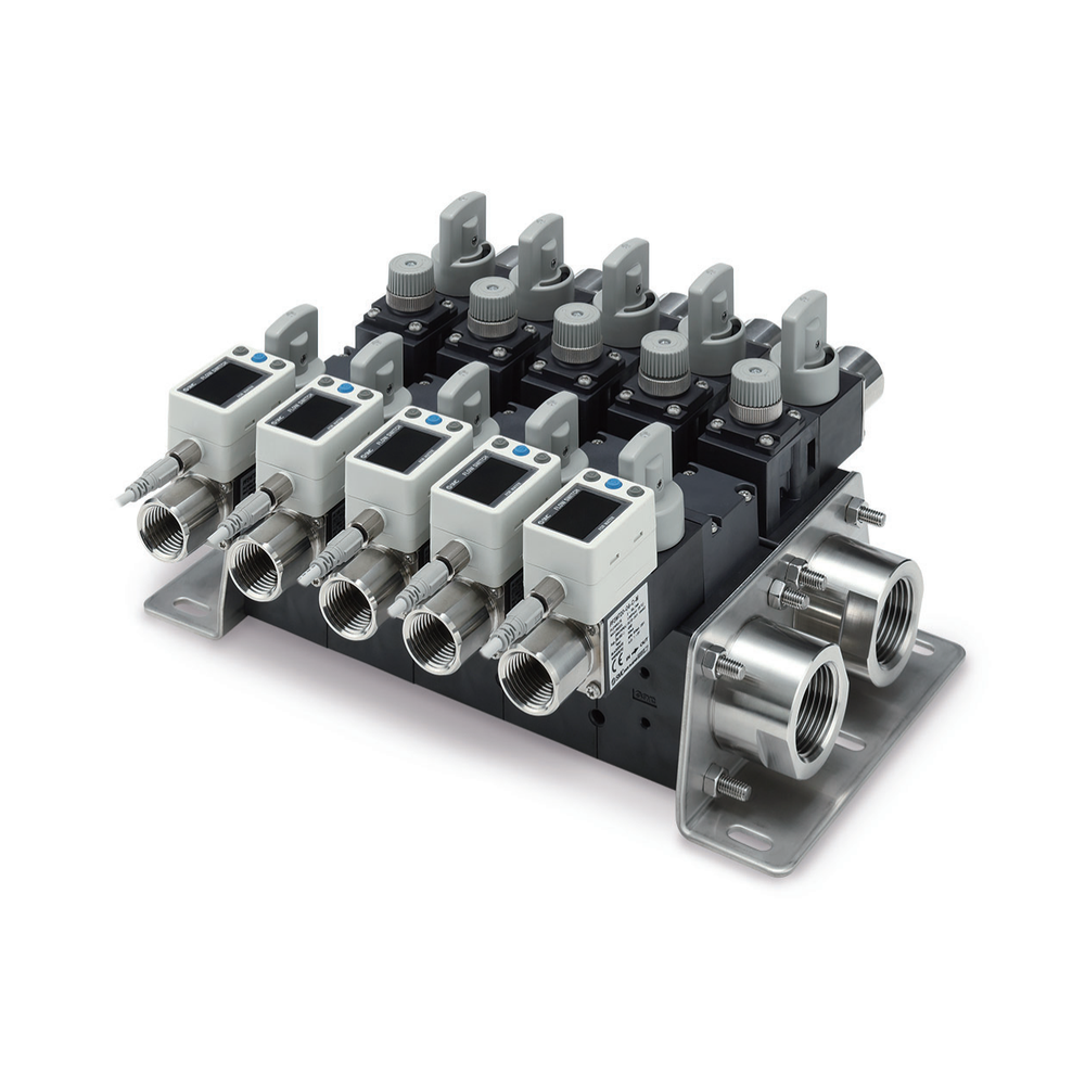
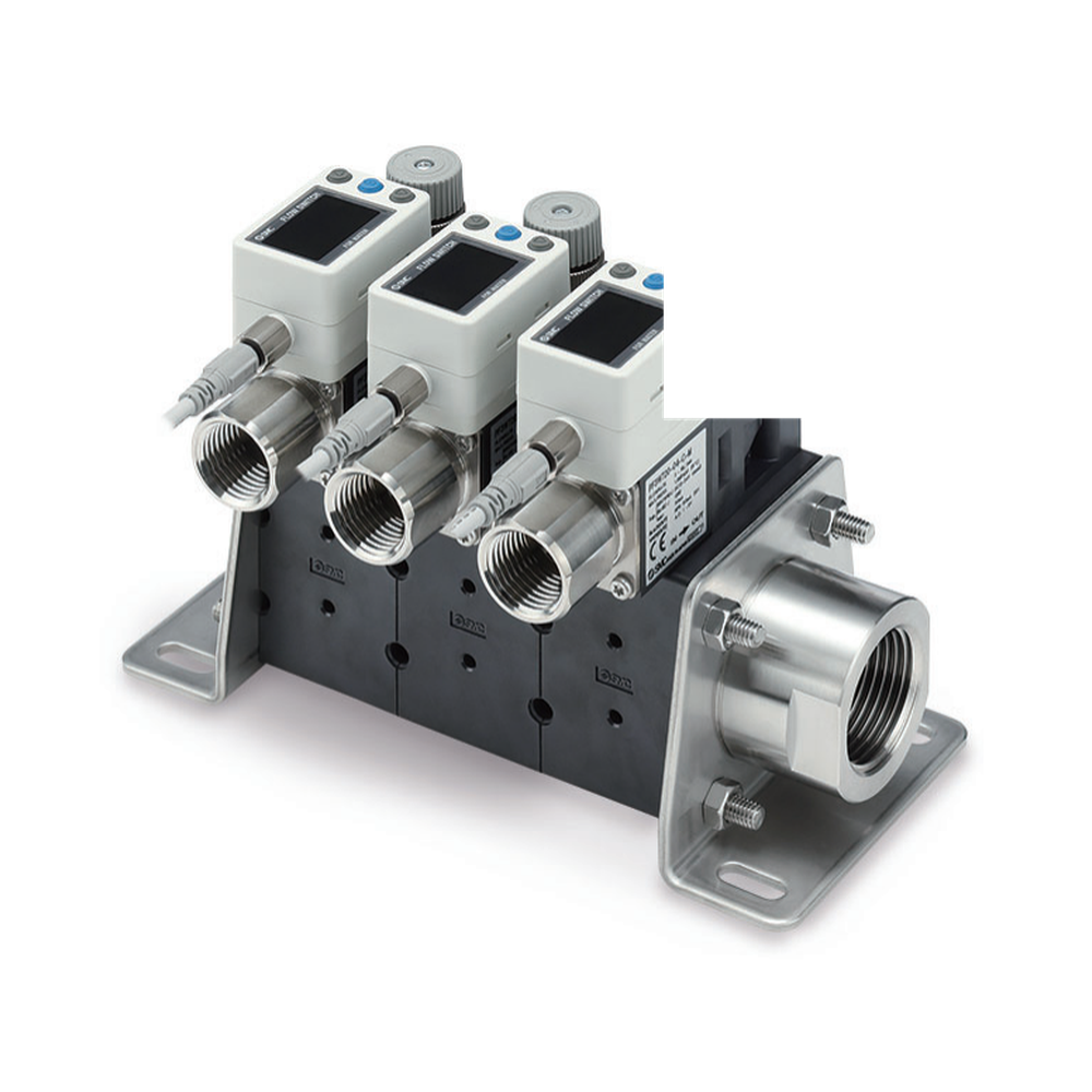
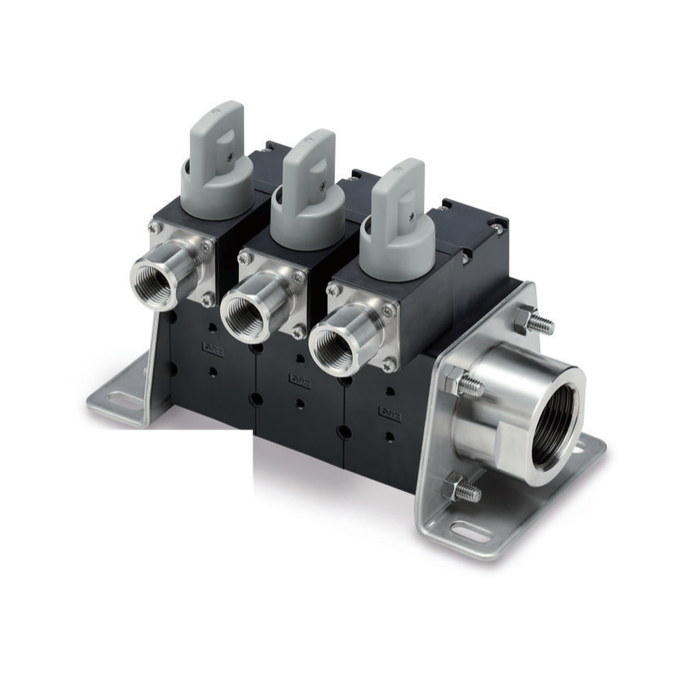
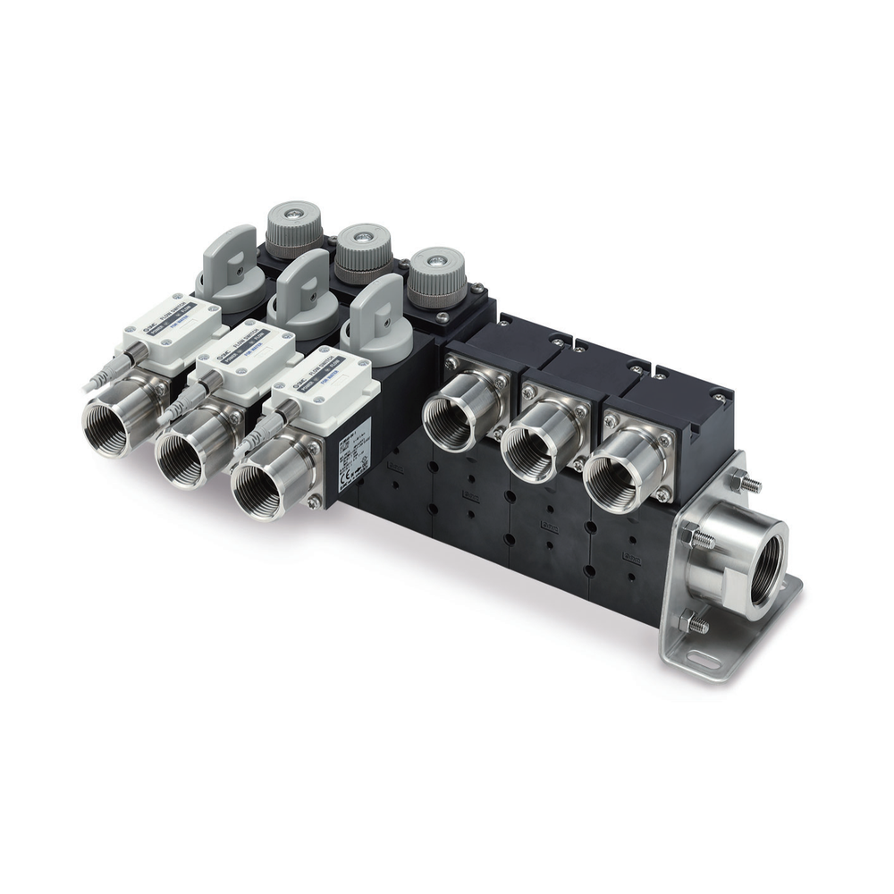
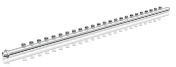
SMC PF3WB integrated basic-type water flow-switch manifold, manufacturer catalogue photograph.
Representative component · configuration-specific

Component selection

All Product drafts

15 results
Private preview · candidate records

15 local draft records. Includes unfinished records and Family overviews. Draft · Noindex. Reference configurations are not approved stock. Image public-use review remains separate.

Show content-ready drafts
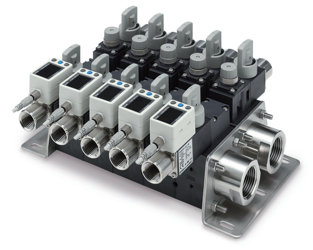
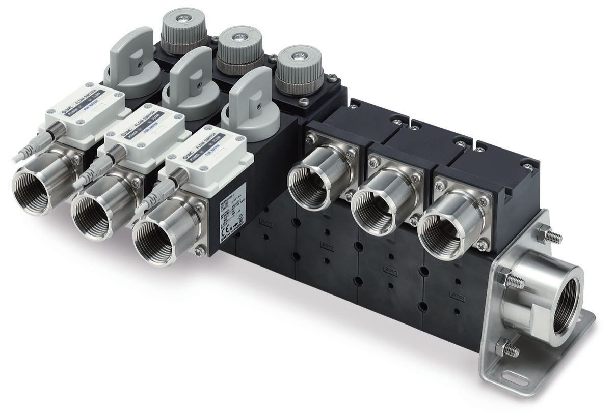
SMC PF3WB integrated basic-type water flow-switch manifold, manufacturer catalogue photograph.

LCP-000099

Basic Integrated Water Flow-Switch Manifold — SMC PF3WB Reference

A supply-and-return water manifold in one basic-layout assembly, with selectable branch flow-switch and valve stations. The photographed configuration represents the PF3WB series,…

Rated flow options
0.5–4, 2–16 or 5–40 L/min per selected flow-switch unit; not the assembled manifold total…
Port size options
1 in main pipe; attachment ports 3/8, 1/2 or 3/4 in, subject to selected…
View specifications
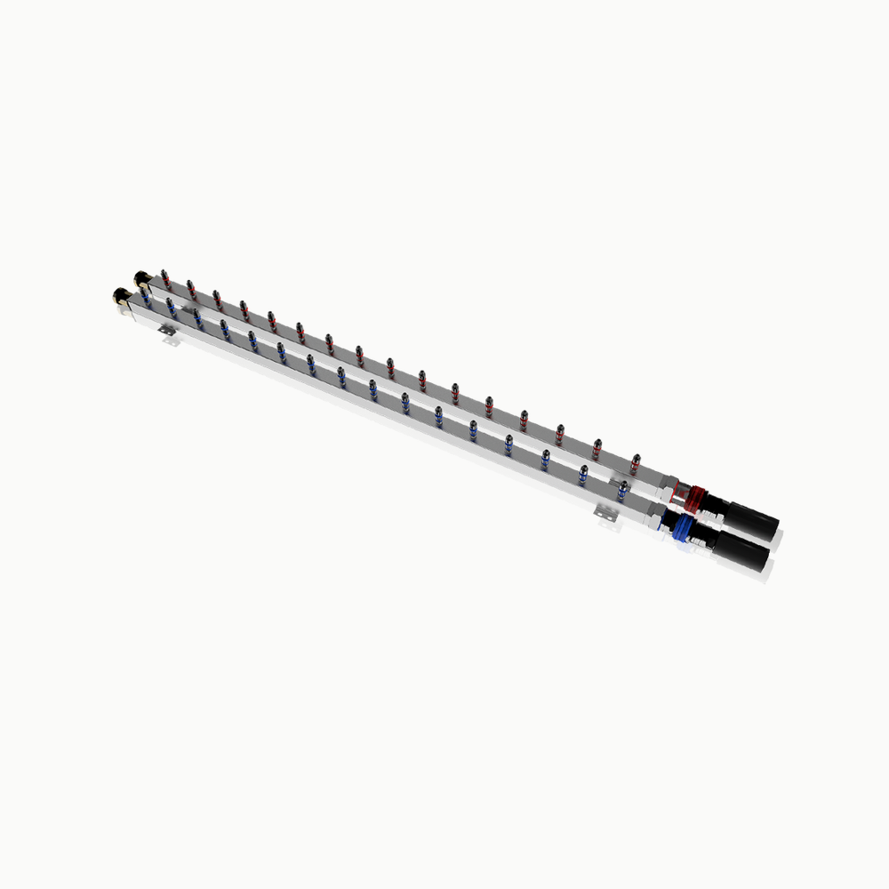
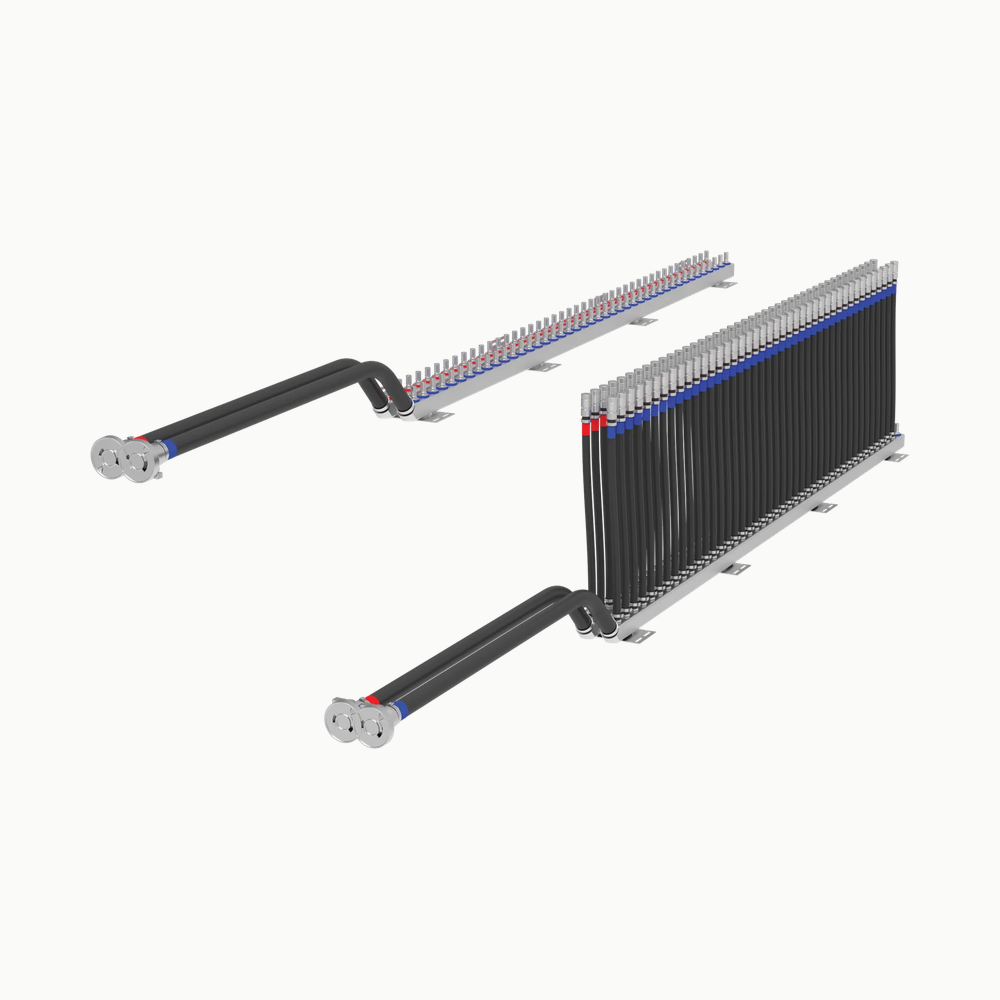
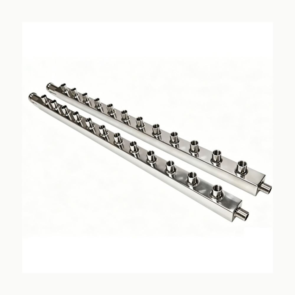
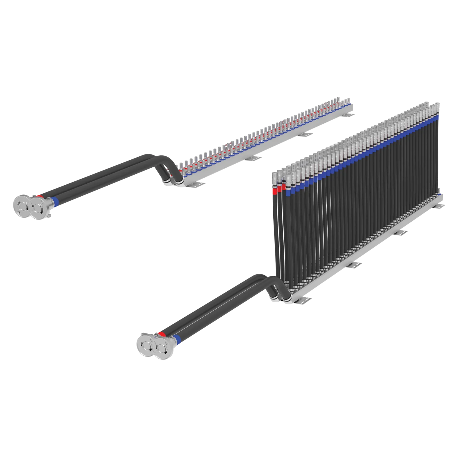
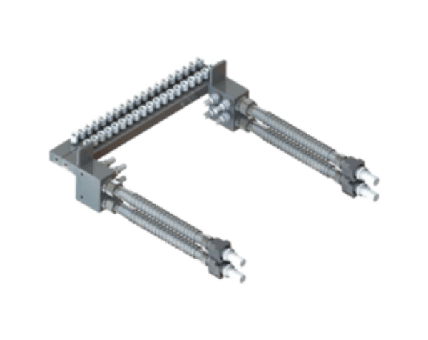
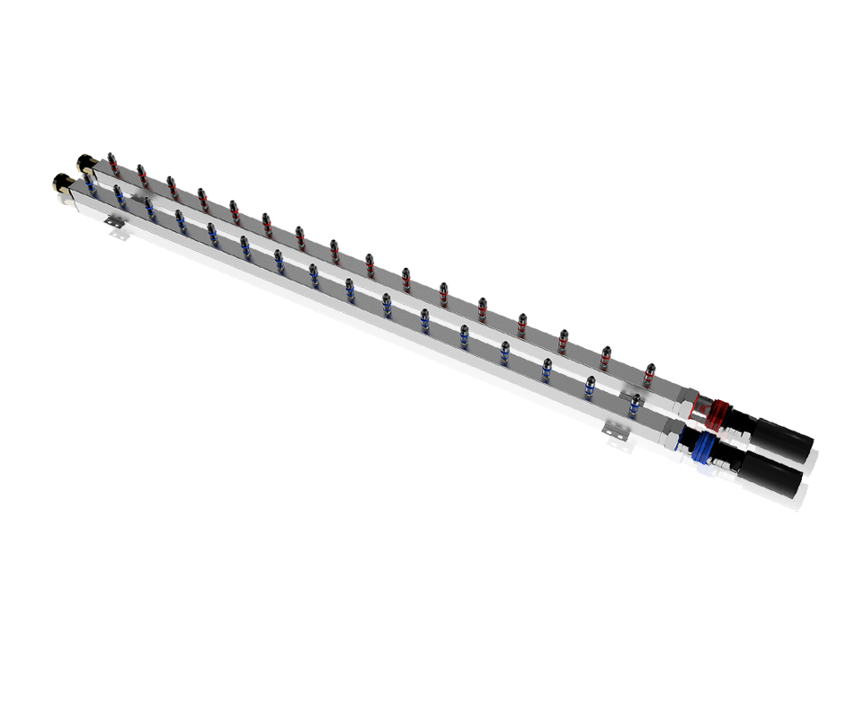
Haiwu paired double-row multi-plug rack manifold — manufacturer product rendering; exact connector and dimensions are project-specific.

LCP-000054

Double-Row Multi-Plug Rack Manifold — Haiwu Reference

A pictured pair of long rack-distribution bars with repeated connectors. Haiwu describes double-row welded manifolds for multi-plug liquid-cooling connections.

Row options
Single-row pipe type for manual plug-in and double-row pipe type for multi-plug connection
Construction
Double-row pipes described as welded
View specifications
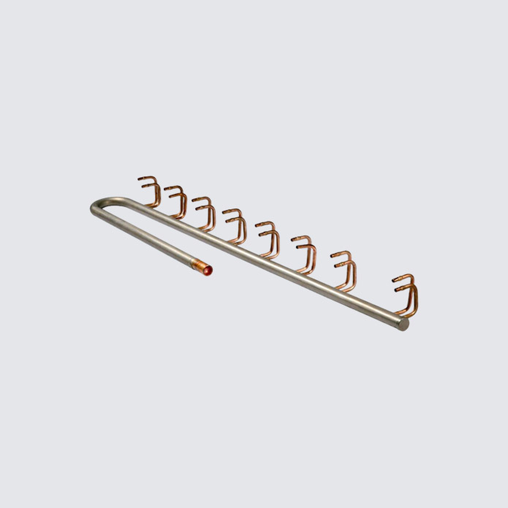
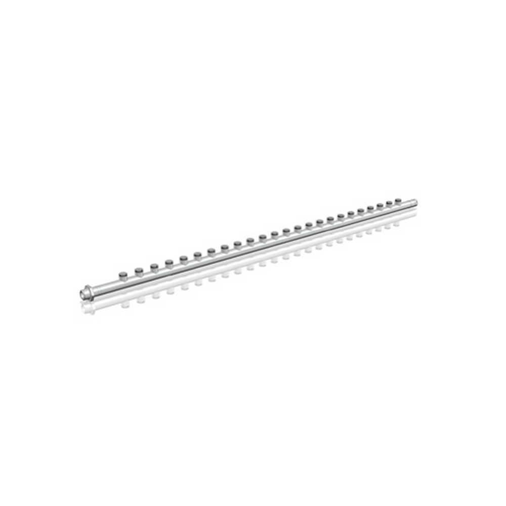
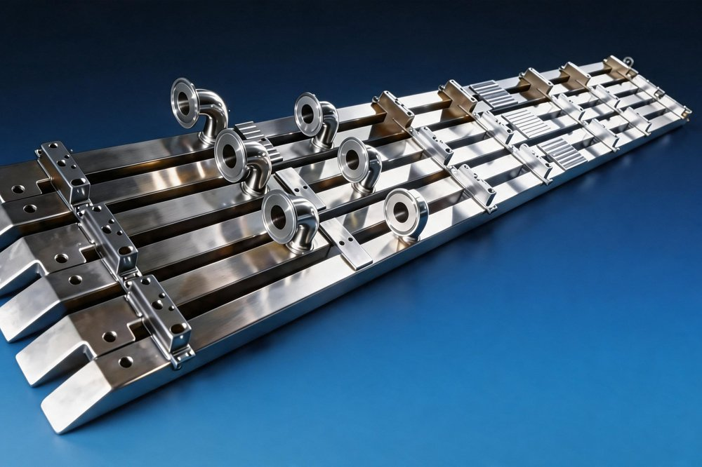
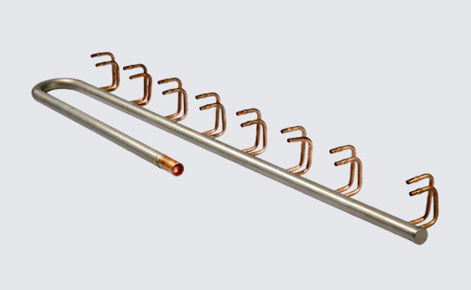
Deya multi-outlet metal branch header with formed small-bore takeoffs, shown as a custom distribution example.

LCP-000071

Drawing-Defined Multi-Outlet Branch Header — Deya Reference

A single long metal header with a row of individually formed takeoffs, shown in a clear standalone manufacturer's photograph. It is a…

Fluid distribution function
A custom stainless header distributes fluid to, or collects fluid from, multiple branches; the…
Custom order basis
Custom stainless headers can be made from a customer's drawing or physical sample
View specifications
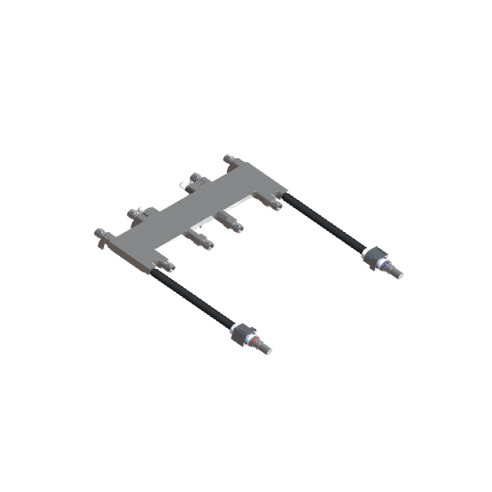
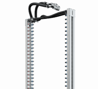
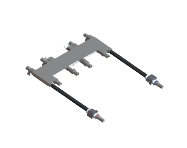
nVent HOFFMAN RackChiller manifold group reference, showing complete long header and hose-whip layouts associated with the RCM42001H page.

LCP-000123

Rack Manifold with Hose Whips — nVent HOFFMAN RCM42001H Reference

A RackChiller rack manifold cataloged as RCM42001H for greater-than-45U racks, with NSP06 quick disconnects, an FD83 supply/return connection and hose-whip layout. The…

Hose length
Supply/return hose: 36 in (914 mm); standard hose whips: 18 in (457 mm)
Supply return pair composition
The rack-manifold set ships as one supply and one return manifold; the RCM42001H row…
View specifications
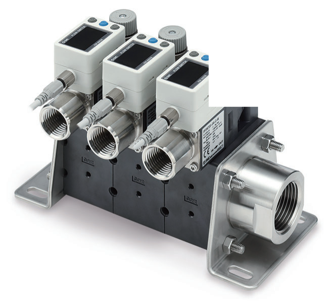
SMC PF3WR remote return-type water flow-switch manifold, manufacturer catalogue photograph.

LCP-000102

Remote Return Flow-Switch Manifold — SMC PF3WR Reference

A return-side unit in SMC's separated water manifold arrangement. The official PF3WR photograph shows individual digital flow-switch stations, unlike the PF3WS supply…

Port size options
1 in main pipe; attachment ports 3/8, 1/2 or 3/4 in, subject to selected…
Wetted parts material
PPS, 304 stainless steel and FKM in the catalogued construction; check selected unit and…
View specifications
SMC PF3WS remote supply-type water manifold, manufacturer catalogue photograph.

LCP-000101

Remote Supply Water Manifold — SMC PF3WS Reference

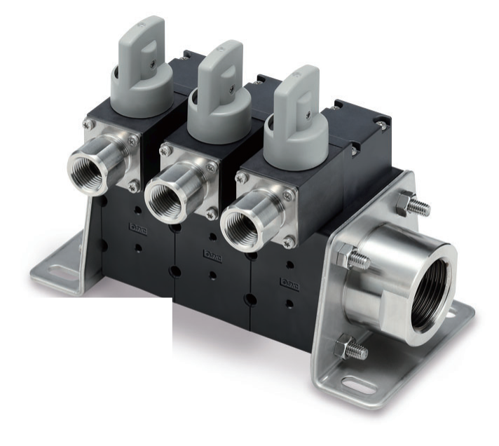
A supply-side unit in SMC's separated PF3WS/PF3WR manifold arrangement. The photographed PF3WS has valve stations without the return-side digital flow displays.

Port size options
1 in main pipe; attachment ports 3/8, 1/2 or 3/4 in, subject to selected…
Wetted parts material
PPS, 304 stainless steel and FKM in the catalogued construction; check selected unit and…
View specifications
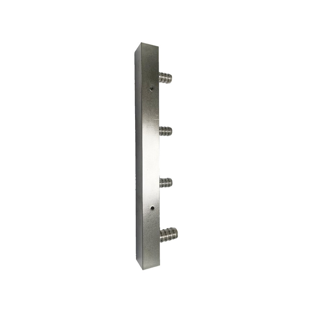
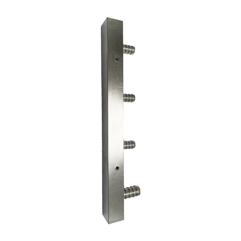
Xinda AI liquid-cooled server manifold — standalone square-body four-branch visual reference; body size, connection standard and material grade are not established by the photo.

LCP-000037

Square-Body Server Rack Manifold — Xinda Reference

A single photographed square-body manifold with four visible hose-barb-style branch outlets. The matching manufacturer page documents internal polishing, single/dual-row layouts and project-defined…

Listed material options
Copper, aluminum or stainless steel listed as alternatives
Body geometry
Seamless square-section manifold body with internally polished fluid path
View specifications

Specify with confidence

The details that shape your selection.

Supply/return arrangement and controlled port map Number, type, size and position of ports Material, rack mounting, envelope and service access Flow distribution and allowable pressure drop at stated conditions Valves/sensors included, assembly drawing, inspection and quantity

  • Function and loop position
  • Interfaces, drawing revisions and envelope
  • Coolant, materials and seals
  • Temperature, pressure and flow conditions
  • Testing and documentation
  • Quantities and delivery requirements

Overview

Rack manifolds distribute supply and return coolant among branches. The port map, mounting envelope and connected devices must be defined together with the flow duty.

Configuration and selection

Prepare a numbered port map, connection schedule, supply/return identification, rack mounting and service access. State operating conditions, allowable pressure drop and any valves or sensors included in the assembly.

Information to prepare

  • Supply/return arrangement and controlled port map
  • Number, type, size and position of ports
  • Material, rack mounting, envelope and service access
  • Flow distribution and allowable pressure drop at stated conditions
  • Valves/sensors included, assembly drawing, inspection and quantity

Configuration and quotation

Include the drawing or specification revision and identify any requirements that are still to be confirmed. Available configurations, testing and documentation are confirmed with quotation.

Documented reference configurations & supporting imagery

Local editorial preview

Documented configurations and product references

Manufacturer examples retain their model and conditions. These references describe source products, not approved stock or supply. Images are pending final selection and rights review.

CoolIT Systems — family reference

ParameterDocumented value / configuration
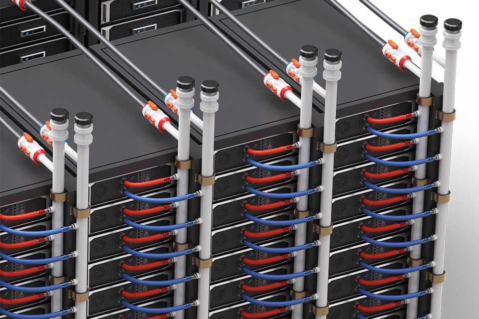
Supply returnRack-mounted distribution routes coolant to individual servers.
MountingMounted to server racks.

Parker Hannifin — family reference

ParameterDocumented value / configuration
Integrated componentsRepresentative manifold assemblies integrate branches with hoses/tubing and quick-disconnect interfaces.

GF Piping Systems — GF whitepaper simulation

ParameterDocumented value / configuration
Port countA 44-branch manifold is used only as a stated simulation example, not as a family default.Conditions: branches: 44

GF Piping Systems — GF in-rack manifold

ParameterDocumented value / configuration
MaterialPVDF
Mountingtop feed; bottom feed
Flow distributionManufacturer describes uniform volume flow across outlet ports; validation remains configuration-specific.
Integrated componentsmain connections; branch ports; quick disconnects; optional air bleed; optional drain
Test conditions100% pressure tested with water before shipment; acceptance pressure/time are not stated in the sheet and must be agreed.

GF Piping Systems — 44-branch simulation

ParameterDocumented value / configuration
Pressure dropSimulation limit below 50 mbar per manifoldConditions: branches: 44; coolant: PG25; couplers: quarter-inch; temperature C: 30

GF Piping Systems — PVDF in-rack manifold / factsheet 04.26

ParameterDocumented value / configuration
Pressure designationPN10Conditions: Custom-engineered manufacturer reference, not site supply specification; limit: Nominal designation; allowable pressure depends on temperature, coolant and final assembly. Page 2 derating curve applies.
Temperature rangemaximum: 80; minimum: -20 °CConditions: Custom-engineered manufacturer reference, not site supply specification; limit: Datasheet temperature limits are not a rectangular PN10 operating envelope; consult page 2 pressure-temperature curve.
Component surface finishRa < 0.5 µmConditions: Custom-engineered manufacturer reference, not site supply specification; scope: Inner surfaces of injection-moulded and extruded components only, not a blanket complete-assembly roughness guarantee

AmpLink — XMF30S4

ParameterDocumented value / configuration
Section size30 x 30 mmConditions: Manufacturer reference only; not a site supply commitment; scope: Listed model column; weight is approximate, not an exact delivered assembly mass.
Tri clamp nominal size1 inConditions: Manufacturer reference only; not a site supply commitment; scope: Listed model column; weight is approximate, not an exact delivered assembly mass.
Estimated weight6 kgConditions: Manufacturer reference only; not a site supply commitment; scope: Listed model column; weight is approximate, not an exact delivered assembly mass.

AmpLink — XMF40S4

ParameterDocumented value / configuration
Section size40 x 40 mmConditions: Manufacturer reference only; not a site supply commitment; scope: Listed model column; weight is approximate, not an exact delivered assembly mass.
Tri clamp nominal size1-1/4 inConditions: Manufacturer reference only; not a site supply commitment; scope: Listed model column; weight is approximate, not an exact delivered assembly mass.
Estimated weight8 kgConditions: Manufacturer reference only; not a site supply commitment; scope: Listed model column; weight is approximate, not an exact delivered assembly mass.

AmpLink — XMF50S4

ParameterDocumented value / configuration
Section size50 x 50 mmConditions: Manufacturer reference only; not a site supply commitment; scope: Listed model column; weight is approximate, not an exact delivered assembly mass.
Tri clamp nominal size1-1/2 inConditions: Manufacturer reference only; not a site supply commitment; scope: Listed model column; weight is approximate, not an exact delivered assembly mass.
Estimated weight11 kgConditions: Manufacturer reference only; not a site supply commitment; scope: Listed model column; weight is approximate, not an exact delivered assembly mass.

AmpLink — XMF30S4 / XMF40S4 / XMF50S4

ParameterDocumented value / configuration
Material options304 / 316L stainless steelConditions: Manufacturer reference only; not a site supply commitment; scope: Manufacturer lists shared options; combinations must be checked against the selected configuration. Design pressure is not proof or burst pressure; temperature and derating are not stated.
Length options1870 / 2000 / 2130 mmConditions: Manufacturer reference only; not a site supply commitment; scope: Manufacturer lists shared options; combinations must be checked against the selected configuration. Design pressure is not proof or burst pressure; temperature and derating are not stated.
Branch count options12 / 18 / 24Conditions: Manufacturer reference only; not a site supply commitment; scope: Manufacturer lists shared options; combinations must be checked against the selected configuration. Design pressure is not proof or burst pressure; temperature and derating are not stated.
Coupling size optionsUQD 04 / 06 / 08Conditions: Manufacturer reference only; not a site supply commitment; scope: Manufacturer lists shared options; combinations must be checked against the selected configuration. Design pressure is not proof or burst pressure; temperature and derating are not stated.
Design pressure0.5 MPaConditions: Manufacturer reference only; not a site supply commitment; scope: Manufacturer lists shared options; combinations must be checked against the selected configuration. Design pressure is not proof or burst pressure; temperature and derating are not stated.
Branch hoseEPDM; 500 mm lengthConditions: Manufacturer reference only; not a site supply commitment; scope: Manufacturer lists shared options; combinations must be checked against the selected configuration. Design pressure is not proof or burst pressure; temperature and derating are not stated.

Beirun / KUNGFLEX — KUNGFLEX liquid-cooling distribution manifold

ParameterDocumented value / configuration
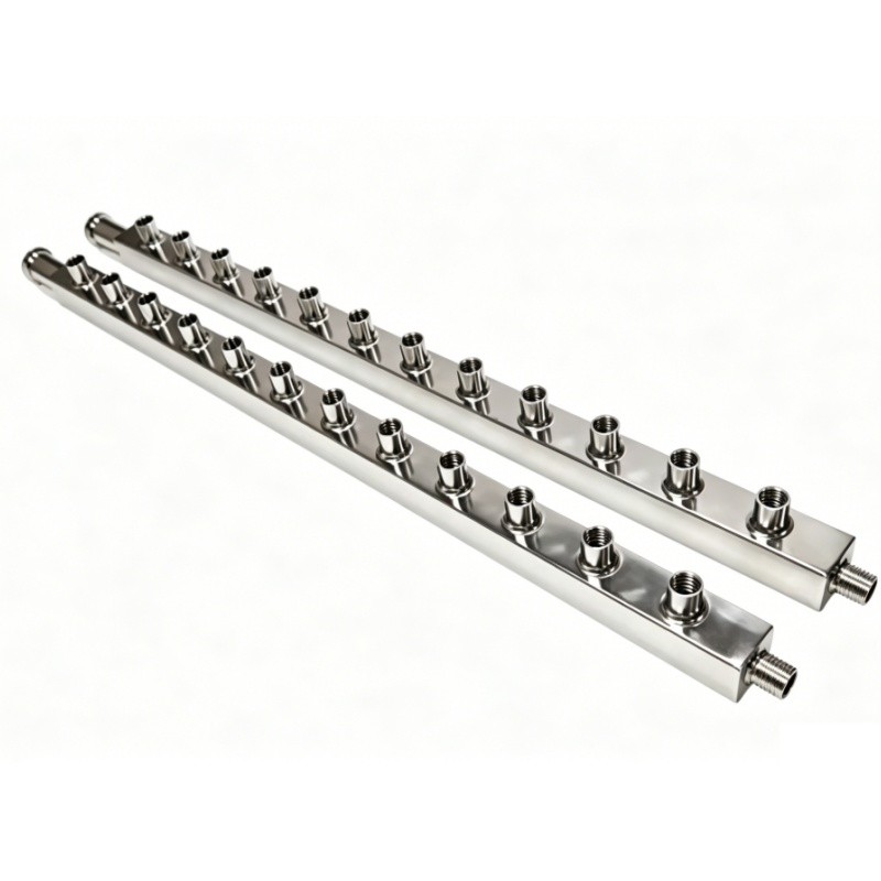
Assembly structureSeparate supply and return manifold bodies for data-center rack cold-plate loopsConditions: scope: Manufacturer series description; pictured pair not tied to a fixed order code
Material options304 or 316 stainless steelConditions: scope: Alternative material grades; do not assume both are used in one assembly
FabricationWelded rectangular manifold bodies with polished finish and branch outletsConditions: scope: Series construction description; weld inspection and pressure test must be specified
Branch port configuration2 to 24 branch ports as project configuration optionsConditions: scope: Customizable range stated by manufacturer; not the port count of the pictured pair
Mounting and end optionsRack side or rear mounting; inlet/outlet and branch connections specified by project drawingConditions: scope: Ordering options; actual fitting type and dimensions not stated for pictured assembly

Xindaaitech — Xinda AI Liquid-Cooled Server Manifold

ParameterDocumented value / configuration
Body geometrySeamless square-section manifold body with internally polished fluid pathConditions: scope: Series description; pictured sample has no fixed drawing or dimensional certificate
Layout optionsSingle-row and dual-row rack manifold configurationsConditions: scope: Options across the supplier series; photo depicts one body, not all layouts
Listed material optionsCopper, aluminum or stainless steel listed as alternativesConditions: scope: Unverified option matrix; photographed body grade cannot be determined visually
Dimension orderingDimensions customizable to customer specificationConditions: scope: No stock length or port count published for pictured configuration

AMX — AMX rack manifold single-row example

ParameterDocumented value / configuration
Pictured structureSingle long manifold body with repeated side branches, shown on the manufacturer's manifold pageConditions: scope: Photograph is a family example, not an exact order code
Row optionsSingle-row and double-row tubing configurations listedConditions: scope: This product page uses a single-row reference image; double-row is a separate configuration option
Listed materialS304 or S316 stainless steelConditions: scope: Table lists both choices across manifold configurations; photographed unit grade not identified
Section options40 × 15, 50 × 25, or 60 × 35 mm listed section sizesConditions: scope: Size options, not measured dimensions of the pictured unit
Port count options2 to 48 branch nodes listedConditions: scope: Project-specific node count; not a count verified from the image
Listed mediaEthylene-glycol solution and purified water listedConditions: scope: Check coolant grade, concentration and complete wetted BOM for a proposed configuration

Haiwu — Haiwu double-row multi-plug rack manifold example

ParameterDocumented value / configuration
Pictured structurePaired long manifold bars with repeated connection points shown in the product imageConditions: scope: Manufacturer does not publish an exact order code for the photographed configuration
Row optionsSingle-row pipe type for manual plug-in and double-row pipe type for multi-plug connectionConditions: scope: Manufacturer description; exact connector series and rack compatibility not established
ConstructionDouble-row pipes described as weldedConditions: scope: Weld process and acceptance criteria are not specified for the photographed configuration
FunctionRack-level coolant distribution to multiple server-side connection pointsConditions: scope: Project branch count, flow balance and mating interfaces need a rack drawing

Deya — Deya pictured custom multi-branch header type

ParameterDocumented value / configuration
Fluid distribution functionA custom stainless header distributes fluid to, or collects fluid from, multiple branches; the manufacturer identifies data-center liquid cooling among its application contextsConditions: scope: Category-level function, not a measured result of the pictured example
Custom order basisCustom stainless headers can be made from a customer's drawing or physical sampleConditions: scope: No fixed dimensions, material grade or pressure rating supplied for the photographed example

SMC — PF3WB Series

ParameterDocumented value / configuration
ConstructionIntegrated basic type combines supply and return in one manifold unit
Pictured configurationManufacturer photograph depicts integrated supply and return with individual flow displays and valve handles
Rated flow options0.5–4, 2–16 or 5–40 L/min per selected flow-switch unit; not the assembled manifold total flow
Station count options1–10 stations; maximum 5 stations when the selected branch flow symbol is 40 (5–40 L/min)
Port size options1 in main pipe; attachment ports 3/8, 1/2 or 3/4 in, subject to selected unit and flow passage
Wetted parts materialPPS, 304 stainless steel and FKM in the catalogued construction; check selected unit and fluid
Published fluid pressure temperatureWater or ethylene-glycol aqueous solution at viscosity ≤3 mPa·s; fluid 0–90 °C; listed operating pressure 0–1 MPa changes with fluid temperature
Supply return unit optionsSupply: flow-adjustment or stop-valve units; return: flow-switch, flow-adjustment or stop-valve units
Mounting dimension basisFront-view mounting-hole positions vary with station count n and selected branch flow-range symbol; use the order-specific dimensional drawing

SMC — PF3WC Series

ParameterDocumented value / configuration
ConstructionIntegrated straight type combines supply and return in one unit with supply and return piping arranged in the same direction
Pictured configurationManufacturer photograph depicts straight-layout unit with flow-sensing and valve stations
Rated flow options0.5–4, 2–16 or 5–40 L/min per selected flow-switch unit; not a whole-manifold rating
Station count optionsSupply 1–5 stations and return 1–5 stations
Port size options1 in main pipe; attachment ports 3/8, 1/2 or 3/4 in, subject to selected unit and flow passage
Wetted parts materialPPS, 304 stainless steel and FKM in the catalogued construction; check selected unit and fluid
Published fluid pressure temperatureWater or ethylene-glycol aqueous solution at viscosity ≤3 mPa·s; fluid 0–90 °C; listed operating pressure 0–1 MPa changes with fluid temperature
Supply return unit optionsSupply: flow-adjustment or stop-valve units; return: flow-switch, flow-adjustment or stop-valve units
Mounting dimension basisStraight-type mounting-hole positions vary with station count n and selected branch flow-range symbol; use the order-specific dimensional drawing

SMC — PF3WS Series

ParameterDocumented value / configuration
ConstructionRemote-type supply manifold intended to be separated from the return unit for flexible layout
Pictured configurationManufacturer photograph shows supply manifold stations with valve handles and no integral flow display
Fluid contextCatalog depicts use with water or ethylene-glycol aqueous solution, fluid temperature 0–90 °C under catalog conditions
Station count options1–10 supply stations; maximum 5 stations when selected branch flow symbol is 40 (5–40 L/min)
Port size options1 in main pipe; attachment ports 3/8, 1/2 or 3/4 in, subject to selected unit and flow passage
Wetted parts materialPPS, 304 stainless steel and FKM in the catalogued construction; check selected unit and fluid
Published fluid pressure temperatureWater or ethylene-glycol aqueous solution at viscosity ≤3 mPa·s; fluid 0–90 °C; listed operating pressure 0–1 MPa changes with fluid temperature
Supply unit optionsSupply side selects flow-adjustment and stop-valve units; flow switches are not applied to the supply unit
Mounting dimension basisRemote supply-unit mounting-hole positions vary with station count n and branch flow-range symbol; use the order-specific dimensional drawing

SMC — PF3WR Series

ParameterDocumented value / configuration
ConstructionRemote-type return manifold separated from the supply unit; pictured with individual digital flow displays
Pictured configurationManufacturer photograph shows return manifold stations with digital flow-sensing modules
Fluid contextCatalog depicts use with water or ethylene-glycol aqueous solution, fluid temperature 0–90 °C under catalog conditions
Station count options1–10 return stations; maximum 5 stations when selected branch flow symbol is 40 (5–40 L/min)
Port size options1 in main pipe; attachment ports 3/8, 1/2 or 3/4 in, subject to selected unit and flow passage
Wetted parts materialPPS, 304 stainless steel and FKM in the catalogued construction; check selected unit and fluid
Published fluid pressure temperatureWater or ethylene-glycol aqueous solution at viscosity ≤3 mPa·s; fluid 0–90 °C; listed operating pressure 0–1 MPa changes with fluid temperature
Return unit optionsReturn side selects flow-switch, flow-adjustment and stop-valve units; IO-Link is limited to compatible integrated-display flow-switch options
Mounting dimension basisRemote return-unit mounting-hole positions vary with station count n and branch flow-range symbol; use the order-specific dimensional drawing

BEEHE — BEEHE MGX node manifold reference

ParameterDocumented value / configuration
Branch interface count19+2 branch/interface count shown in the MGX column
Envelope dimensions524.5 × 389.8 × 125.4 mm listed for the MGX column
Body pipe materialSUS304 body and SUS316 piping listed in the MGX column
Documented supply distribution modeThe maker describes the node-manifold family as generally using one supply inlet to distribute to multiple branch outlets, with branch quick connections to internal cooling devicesConditions: scope: Series-level typical routing; MGX project drawing must confirm whether a separate return manifold is included

BEEHE — BEEHE GB200 node manifold reference

ParameterDocumented value / configuration
Branch interface countTwo branches listed in the GB200 column
Envelope dimensions431.6 × 64.5 × 30.2 mm listed in the GB200 column
Body pipe materialSUS304 body and SUS316 piping listed in the GB200 column
Documented supply distribution modeThe maker describes the node-manifold family as generally using one supply inlet to distribute to multiple branch outlets, with branch quick connections to internal cooling devicesConditions: scope: Series-level typical routing; GB200 project drawing must confirm whether a separate return manifold is included
Supply distribution modeManufacturer describes the inner-manifold family as generally using one inlet to distribute to multiple outlets; the GB200 column separately lists two branches. Exact supply/return pairing for a pictured build requires a drawing.Conditions: scope: General manufacturer description, not a GB200 order-code hydraulic schematic or claim that both pictured legs are supply outlets
Mounting methodScrew mounting, as listed in the GB200 platform columnConditions: scope: Platform-column reference; hole pattern and mounting datums are not published
Branch external interfacesNVQD04 branch interface and NVQD04 external interface, as listed in the GB200 platform columnConditions: scope: Interface designations only; actual mating part numbers and revision require drawing confirmation
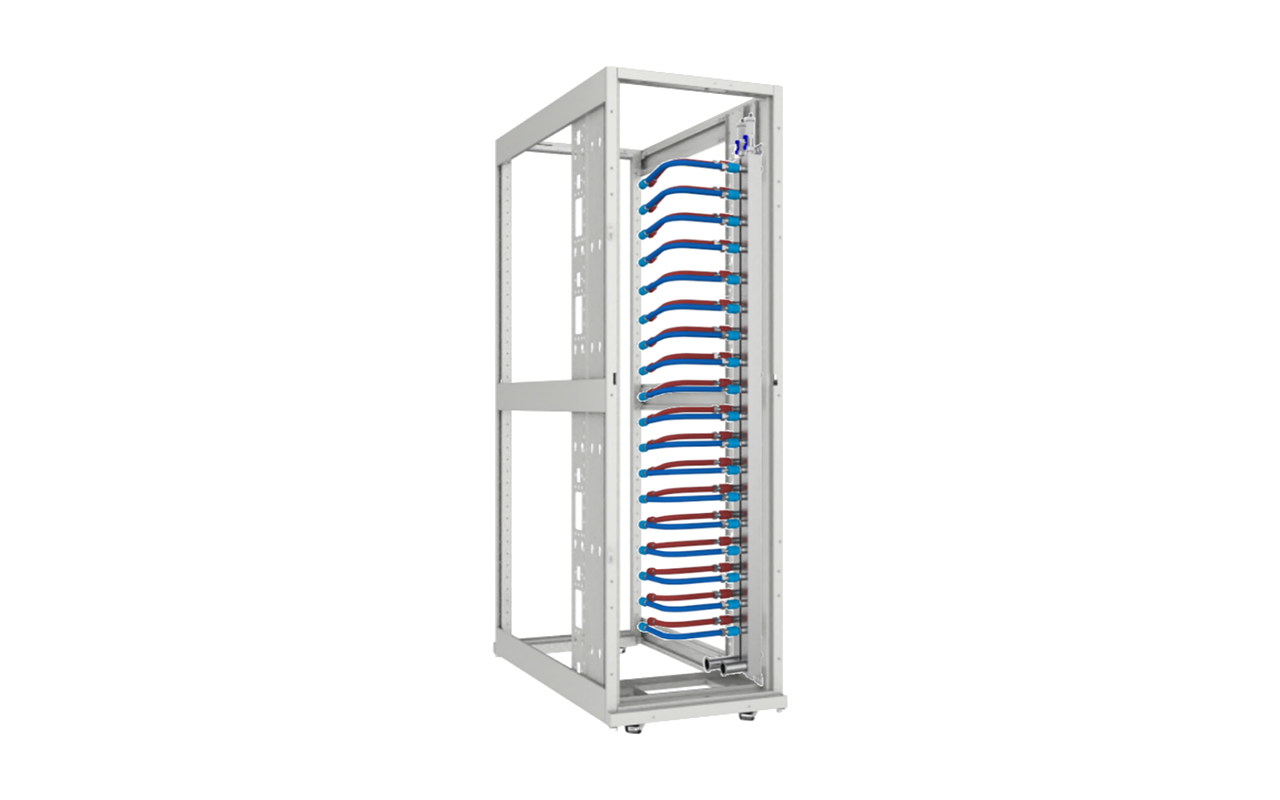
Manufacturer pressure reference10 bar stated as pressure-bearing reference in the GB200 platform columnConditions: scope: Manufacturer table only; working/test/burst basis and temperature/coolant conditions are not defined. Not a site supply or complete-loop rating

BEEHE — BEEHE Rubin node manifold reference

ParameterDocumented value / configuration
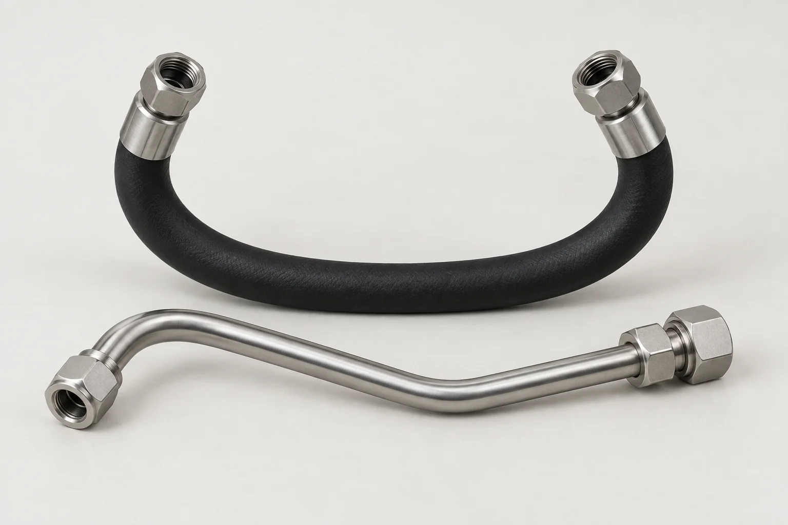
Branch interface countFive branches listed in the Rubin column
Envelope dimensions432.8 × 139 × 41.8 mm listed in the Rubin column
Body pipe materialSUS304 body and SUS316 piping listed in the Rubin column
Documented supply distribution modeThe maker describes the node-manifold family as generally using one supply inlet to distribute to multiple branch outlets, with branch quick connections to internal cooling devicesConditions: scope: Series-level typical routing; Rubin project drawing must confirm whether a separate return manifold is included

nVent HOFFMAN — RCM42001H

ParameterDocumented value / configuration
Product identityRack manifold with standard hose whips for greater-than-45U rack
Connector scheduleNSP06 quick disconnect connectors; FD83 supply/return connector
Hose lengthSupply/return hose: 36 in (914 mm); standard hose whips: 18 in (457 mm)
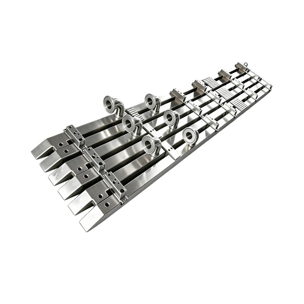
Supply return pair compositionThe rack-manifold set ships as one supply and one return manifold; the RCM42001H row is the hose-whip configuration for racks greater than 45UConditions: scope: Maker catalog set composition; verify exact port count and routing on the approved order drawing
Header material and port formThe series specifications list 1.50 × 1.50 in (38 × 38 mm) stainless-steel tube construction and friction-drilled ORB-6 port threadsConditions: scope: Series construction associated with the listed manifold configurations; does not establish branch count or flow rating
Mounting brackets and hardwareThe manifold set includes two sets of mounting brackets, four brackets in total, with hardware; button-style universal mounting is describedConditions: scope: Bracket quantity from maker group catalog; actual rack fit and location require installation drawing

Configuration options and selection inputs

Port map

Port arrangement is driven by server-board/rack architecture and must be captured as a project-specific map.

Reference: CoolIT Systems — family reference

Supply return

In-rack manifold routes coolant to server trays; supply/return arrangement is a project configuration input.

Reference: GF Piping Systems — family reference

Port map

Customer-specific dimension, length, ports and QD arrangement; top or bottom feed and optional bleed/drain/special ports.

Reference: GF Piping Systems — family reference

Connection

Main connection, quick disconnect and special-port choices are customer-specific.

Reference: GF Piping Systems — family reference

Geometry rfq inputs

Maximum length, available width/depth, outer diameter, outlet count, initial port offset u0 and subsequent spacing u1; attach a drawing for non-uniform spacing.

Reference: GF Piping Systems — PVDF in-rack manifold / M1161 enquiry sheet

Conditions: Custom-engineered manufacturer reference, not site supply specification; scope: Required design inputs, not fixed catalog dimensions

Connection rfq inputs

Specify the exact quick-disconnect interface, nominal diameter and thread connection; listed supplier alternatives do not imply cross-brand interchangeability.

Reference: GF Piping Systems — PVDF in-rack manifold / M1161 enquiry sheet

Conditions: Custom-engineered manufacturer reference, not site supply specification; scope: Manufacturer blank enquiry form options; compatibility still requires matching interface drawings

Loop rfq inputs

Coolant and safety data sheet, minimum/maximum pressure and temperature, required flow per outlet and inlet/outlet temperature difference.

Reference: GF Piping Systems — PVDF in-rack manifold / M1161 enquiry sheet

Conditions: Custom-engineered manufacturer reference, not site supply specification; scope: Per-project declared operating conditions; no default operating flow or heat load

Feed and service options

Top or bottom feed, straight or 90-degree feed geometry, orientation, end cap, vent or drain; define the installed routing.

Reference: GF Piping Systems — PVDF in-rack manifold / M1161 enquiry sheet

Conditions: Custom-engineered manufacturer reference, not site supply specification; scope: Custom-design inputs in the enquiry sheet; each arrangement requires drawing confirmation